To create a new figure, you can use the Line ![]() , Sector
, Sector
![]() , Arc
, Arc ![]() , and Spline
, and Spline ![]() tools
from the toolbar.
tools
from the toolbar.
Choose a tool and use a mouse to draw a segment.
To add another segment to it, start drawing from one of the endpoints of the existing one.
This will lengthen the geometry.

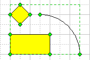
If you start drawing a segment at any position with Ctrl (in Windows) or Cmd (in Mac OS) held down, this segment will be assigned to the currently selected figure, expanding it with a new geometry. So, the figure may consist of two (or more) separate geometries, but it's still one figure.
If you hold down the Shift key when drawing, the constrained drawing mode switches on. The way in which the constrained segments behave depends on the segment type.
Basic Segments
![]() Line To: a
line segment. It can be created with the Line tool. To constrain a line
to any 45-degree angle, hold down the Shift key as you drag.
Line To: a
line segment. It can be created with the Line tool. To constrain a line
to any 45-degree angle, hold down the Shift key as you drag.
Note: To switch to the Line tool, you can also select Line
Segment from the Tools / Draw menu, or press Ctrl+3.
![]() Sector To:
a circular sector. It can be created with the Sector tool. The
direction in which you first drag the mouse determines which way the curve bows. The point
where you release the mouse button defines the other endpoint of the sector. To change the
direction in which the curve bows, hold down the Shift key when you drag.
Sector To:
a circular sector. It can be created with the Sector tool. The
direction in which you first drag the mouse determines which way the curve bows. The point
where you release the mouse button defines the other endpoint of the sector. To change the
direction in which the curve bows, hold down the Shift key when you drag.
Note: To switch to the Sector tool, you can also check Sector
Segment in the Tools / Draw menu, or press Ctrl+4.
![]() Arc To:
an elliptical quarter segment. Use the Arc tool to create it.
Arc To:
an elliptical quarter segment. Use the Arc tool to create it.
Note: To switch to the Arc tool, you can also select Arc
Segment from the Tools / Draw menu, or press Ctrl+5.
![]() Spline To:
a smooth curve (also called spline). It can be created with the Spline
tool. This tool works like a pencil on paper, the only difference is that the curve results is smooth rather than jagged. Once drawn, the spline is easy to
modify by adjusting its vertices and adjustment handles.
Spline To:
a smooth curve (also called spline). It can be created with the Spline
tool. This tool works like a pencil on paper, the only difference is that the curve results is smooth rather than jagged. Once drawn, the spline is easy to
modify by adjusting its vertices and adjustment handles.
Note: To switch to the Spline tool, you can also check Spline
Segment in the Tools / Draw menu, or press Ctrl+6.
Elementary Figures
Besides single segments, you can also draw some widely-used figures: rectangle, ellipse, Text object. Use the corresponding toolbar buttons for each of them.
![]() Rectangle:
creates a filled rectangle. Drag the mouse to change its size. By holding down the Shift
key as you draw, you constrain the rectangle to a square.
Rectangle:
creates a filled rectangle. Drag the mouse to change its size. By holding down the Shift
key as you draw, you constrain the rectangle to a square.
Note: To switch to the Rectangle tool, you can also use
the Tools / Draw / Rectangle menu or press Ctrl+7.
![]() Ellipse:
draws a filled ellipse. Drag the mouse to determine its size. By holding down the Shift
key as you drag, you constrain the ellipse to a circle.
Ellipse:
draws a filled ellipse. Drag the mouse to determine its size. By holding down the Shift
key as you drag, you constrain the ellipse to a circle.
Note: To switch to the Ellipse tool, you can also use the Tools
/ Draw / Ellipse menu or press Ctrl+8.
![]() Edit Text: creates a "Text" object. Drag the mouse to
determine the size of the box. If you hold down the Shift key as you
drag, you will get a square box. After you release the mouse button, the Edit Text
mode switches on, and you can type the text in the box.
Edit Text: creates a "Text" object. Drag the mouse to
determine the size of the box. If you hold down the Shift key as you
drag, you will get a square box. After you release the mouse button, the Edit Text
mode switches on, and you can type the text in the box.
Note: To switch to the Edit Text mode, you can also check Text
in the Tools / Draw menu.
In any other tool mode, you can activate the text editing mode for a while: just
select the needed object and or press F2. And when you finish editing
text, press F2 or Esc.
Additional Operations on Figures
In ConceptDraw, figures may consist of multiple segments. Several segments joined together are called geometry. A figure may contain more than one geometry.
The Figure / Operations menu holds the commands for working with
figures and geometries.
To create complex figures, you can use the Combine operation to make up a
figure consisting of several geometries.
This operation can be reversed by the Scattering command which splits a
complex figure into separate geometries.
The Join operation lets you merge the segments with coinciding endpoints
into one geometry, and also form a closed figure by merging separate segments of its
contour.
Combine
The Combine operation is a special case of grouping: it is applied only to figures, and groups them into a complex figure with a unified line and fill formatting of all its geometries.
If you want to make up a complex figure by grouping
several figures that have the same properties (fill color, line
color, line thickness, etc.), select these figures and use the Combine
operation: Figure / Operations / Combine.
When the properties of the figures are the same, it is better to Combine
them rather than Group: combined figures take up less space when saved.
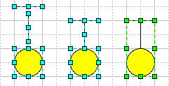
If overlapping figures are combined, the overlapping areas become transparent. This feature is extremely useful for creating "holes" in the closed figures.
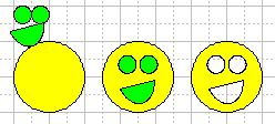
Note: If you combine figures having different line and fill properties, all the elements will be formatted after the primary selected figure.
Join
The Join operation (Figure / Operations / Join) lets
you merge several selected figures into one. All the elements
take a unified formatting after the primary selected figure.
The essential difference from the Combine operation is that if a solid
path results after the operation, it becomes a single geometry. So when several geometries
have some coinciding endpoints, the Join operation merges them into one
geometry. (The Combine operation just groups figures with the same
properties, but never merges them.) That is why when a closed figure results after the Join
operation, it is filled automatically (this never happens when the figures are combined).
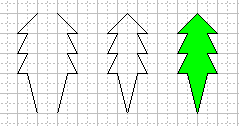

Note: Be sure to superpose the endpoints precisely
(they must have the same coordinates). The Snap mode ![]() is very helpful for this purpose.
is very helpful for this purpose.
You can see the difference between the Combine and Join operations from the illustration below:

Note: If the geometries joined can not be merged into one (if they have no coinciding endpoints), the Join operation works in the same way as Combining. And since the resulting figure in this case consists of several geometries, it can be split into separate geometries by Scattering.
Scattering
Figures may consist of several geometries (each geometry is a solid path of joined segments).
The Scattering operation (Figure / Operations / Scattering)
lets you split a complex figure into separate geometries,
so it is inverse to the Combine operation. If a figure consists of
several geometries, the Scattering operation will form a separate object
for each geometry of the figure. It looks like dividing a figure into parts it consists
of.
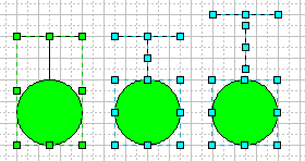
Note: The Scattering operation takes
no effect if you try to split a single geometry (for instance, if one resulted
after the Join operation).
To split a single geometry into parts, you should first divide it into several geometries:
activate the Insert Vertex tool ![]() , and holding down Ctrl
(in Windows) or Cmd (in Mac OS), click to indicate the
points where you want to separate the geometry. Then perform Scattering.
, and holding down Ctrl
(in Windows) or Cmd (in Mac OS), click to indicate the
points where you want to separate the geometry. Then perform Scattering.
See also:
Using Handles to Change the Appearance of Objects
- Reshaping Figures
Facilities for Precision in Drawing
ConceptDraw offers you several handy implements for precise drawing.
The Grid provides accuracy in drawing, positioning and measuring objects.
For better precision in drawing and positioning objects, you can make the objects snap
to the grid lines and nodes, as well as to connection points of objects,
etc.
The gluing lets you keep the objects connected when you
manipulate them. You can glue the objects to the guide lines dragged out
of the rulers, to make the objects move together with the guide line.
Grid
Snapping
Guide Lines
Gluing
Grid
The Grid is made up by thin lines crossing the document at equal
intervals.
The grid lines are helpful for precise drawing and positioning
objects in the document.

You can show / hide the grid in the document: use the Grid option in the View menu.
If the Snapping ![]() mode is active, the
grid will pull the pointer when you manipulate objects.
mode is active, the
grid will pull the pointer when you manipulate objects.
When you drag a handle, the mouse pointer will jump to the nearest grid node or the cell
centre.
When moving an object, the same occurs to its alignment box. This helps you position
objects precisely.
(See the "Snapping" section for more
detail.)
Note: For more precise and detailed drawing, it is also useful to set a higher Zoom level: see "Zooming a Page".
You can assign the grid color for the entire application. Use the Preferences
dialog to do that:
select Preferences from the Edit menu, then open the Miscellaneous
tab, and use the Grid Color button to set the desired color.
Grid Parameters
To set the grid parameters, you can use the Grid Properties dialog from the Tools / Grid menu.
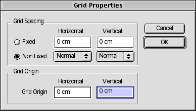
The Grid Spacing section lets you adjust the horizontal and vertical spacing for the grid in the active document.
You can use either of the two modes for grid spacing: Fixed or Non-Fixed.
The Non-Fixed mode is the most convenient and widely used. In this
mode, the grid spacing remains visually the same regardless of the magnification, which
increases the accuracy with each higher zoom level. For instance, if the spacing is 0.5 cm
at 100%, it will be made 0.25 cm at 200% (the new grid lines will be added between the
existing ones).
You can specify separate settings for the width and height of a cell in grid. The
following options are available: Fine, Normal, Coarse.
Another grid mode is the Fixed Grid mode. In this case the grid
spacing is a fixed value, and changes visually with the magnification.
You set a specific distance between the grid lines (horizontal and vertical separately).
This value is preserved regardless of magnification, though visually the distance changes
with the zoom level.
Note! If you want the grid to be printed, use the Fixed mode. The Non-Fixed grid is not printed.
The Grid Origin section lets you set the point on page from which the grid
lines should be built.
By default, the grid is built from the top left-hand corner of the document page.
If you need to shift the grid to some distance (usually smaller than the current measuring
unit) from the top left-hand corner of the document page, specify the values for the
horizontal and vertical shift. The node of the grid will be placed at the point you
specified, and the horizontal and vertical grid lines will be built in either direction
from this point.
Note: If you need to work constantly with a specifically formatted grid, save these settings in a template file, and create new documents from this template.
Snapping
The Snapping mode makes the mouse pointer jump into position of the nearest snap location. This feature is used for positioning objects precisely with respect to the grid lines, ruler subdivisions, connection points of objects, etc.
Use the Snap On/Off ![]() button on the toolbar to turn the Snapping on/off.
button on the toolbar to turn the Snapping on/off.
Note: You'll definitely welcome the possibility of turning Snap
on/off on the fly.
In any tool mode, you can invert the Snap mode by holding down the Alt
key (in Windows) or Cmd
key (in Mac OS). This helps you increase precision of your drawing in an easy
way.
By default, the pointer snaps to the grid lines and nodes, to the guide lines and to the connection points of objects. You can also set other locations to which the pointer will snap: ruler subdivisions, handles of objects, geometries and vertices of figures. For these settings, use the Snap&Glue dialog (Tools / Snap&Glue).
Snap&Glue Settings
The Snap&Glue dialog lets you specify the options for Snapping
(set the locations to which the pointer will snap),
and turn on/off the Snapping and Gluing modes for the
active document.
To call this dialog, use the Snap&Glue option from the Tools menu.
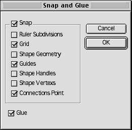
The Snap check box lets you turn Snapping on/off.
The Glue check box can be used to turn Gluing on/off.
When Snapping is active, you can set the locations to which the pointer will snap.
If the Snap To Grid option is enabled, the grid will pull the
pointer when you manipulate objects. When you drag a handle, the mouse pointer will jump
to the nearest grid node or the cell centre. When the entire object is moved, the same
occurs to its alignment box. This helps you position objects precisely.
This option is active by default.
If Ruler Subdivisions is the only option enabled, the pointer will snap to the imaginary lines coming out of the rulers' subdivisions. Use this for very precise positioning.
If the Figure Geometry option is checked, the object you move or resize snaps to the contours of other objects. It is usually helpful when you need to attach an object to another object.
If the Snap To Guide option is on, the pointer snaps to the guide lines. This option is active by default.
The Figure Handles option makes the pointer snap to the nearest resize handle of an object.
The Figure Vertices option makes the pointer snap to the nearest vertex of an object.
If the Connection Points option is on, the pointer snaps to the nearest connection point of an object. this option is active by default.
Even if the Snapping is enabled, the pointer starts jumping to a snap location
only within a certain distance to the location.
The default value is 15 pixels. If you need to change it for the particular active
document, use the File / Document Properties (the Settings
tab). If you want to set a specific Snap Sensitivity distance for all
future documents, specify the new value in the in the Edit /
Preferences dialog (see the Default tab).
Guide Lines
Sometimes you may need to align objects along a line, and retain this alignment when
moving all these objects.
This is possible by gluing objects to a Guide Line. After you glue the
objects, you can move the guide line, and they all will be moved together with it.
A Guide Line is a special ConceptDraw object which is used for aligning objects and positioning them precisely.

To insert a horizontal or vertical guide line in your document, click on the
corresponding ruler (horizontal or vertical) and drag a line out of it. Drop the guide
line in the position where you need to put it.
You can manipulate (select, move, duplicate, delete) guides in the same way as other
objects.
You can glue objects to a guide line by their alignment
boxes. The Gluing mode ![]() is active by default.
is active by default.
(For more detail on using the Gluing mode, see the "Gluing"section.)
To glue an object to a guide line, just move the object to the place on the guide you want to glue it to. After you release the mouse button, the resize handles on the glued side of the object turn red indicating the object is glued to the guide.
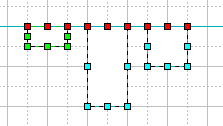
So, by gluing objects to a guide you may then reposition them at once keeping their
relative distances.
To unglue an object, just drag it away from the guide line.
Note: Guide lines are not printed.
Gluing
The Gluing mode (which is active by default) makes objects
remain connected even if one of them is moved.
Unlike Snapping, the Gluing mode establishes the connection after you
release the mouse button, and maintains it when you manipulate the objects.
To provide precise positioning of objects and handles, it's usually a good idea to use Gluing
together with Snapping.
To enable/disable the Gluing, use the Glue On/Off
![]() button on the toolbar or check the
corresponding option in the Snap&Glue dialog (Tools /
Snap&Glue).
button on the toolbar or check the
corresponding option in the Snap&Glue dialog (Tools /
Snap&Glue).
You can glue
- objects and control handles to guide lines,
- endpoints of connectors to the connection points of objects,
- object's control handles to the connection points of other objects.
Gluing Objects and Control Handles to a Guide Line
If you need to align objects along a line and move all these objects together
with the line, - glue these objects to a Guide Line. Then you can move the guide
line, and the glued objects will be moved accordingly with the guide.
Activate the Gluing mode and move the object to the place on the guide you want
to glue it to. After you release the mouse button, the resize handles on the glued side of
the object turn red indicating the object is glued to the guide.

You can glue control handles of objects to a guide line. Activate the Gluing mode, move the control handle to the guide line and release the mouse button. When glued, the control handle turns red. When you move the guide line, the glued control handles move with it.
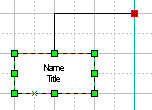
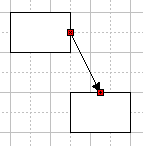
Gluing Endpoints of Connectors to the Connection Points of Objects
This is one of the main functions of gluing. When you glue the endpoints of connectors
to the connection points of the objects, the connection will be maintained even when the
objects are repositioned or resized.
See "Connecting Objects" for more detailed
information.
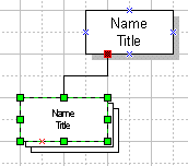
Gluing Control Handles to Connection Points of Objects
This is an extremely important function of gluing.
It lets you add connectors to a group, so that the connectors remain functional within the
group. (If you simply group an object with a connector attached to it, the loose end of
the connector will no longer glue to other objects.)
If you want the connector to remain functional within a group, you should add
a Control Handle to the group, attaching it to the loose end of the
connector. Then you can glue the resulting new handle to connection points of other
objects in the same way as you glue the endpoints of connectors.
To glue a control handle to a connection point of an object, turn Glue on
and move the control handle to the needed connection point of the object. On releasing the
mouse button, the control handle turns red, indicating that it is glued. Now when
you move the object, the connection will be maintained.
See also:
What Objects You Can Use
Pictures
Grouping Objects
See related topics:
Manipulating Objects
Using Handles to Change the Appearance of Objects