

Connectors
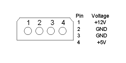
The DC power connector is designed to mate with AMP part 1-480424 (using
AMP pins P/N 350078-4). Equivalent assignments are shown below, viewed
from the end of the drive.

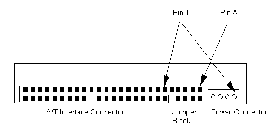
AT I/F connector
The drive uses single-ended drivers and receivers.
The connector is designed to mate with 3M part 3417-7000
or equivalent.

Note: A/T = IDE
Note: It is intended that the drive
should only be in electrical contact with the chassis
of a designated set of mounting holes. Other electrical
contact may degrade error rate performance. As a result
of this it is recommended that there should be no metal
contact to the drive except at the mounting
holes or the side rails into which the mounting holes
are taped.
Cabling
The maximum cable length from the host system to the drive, plus the circuit pattern length inside the host systems, must not exceed 18 inches (45.7 cm).
For higher data transfer application (>8.3 MB/sec) a consideration in system design is recommended to reduce cable noise and/or cross-talk, such as; shorter cable, bus termination, shielded cable, etc.
Signal definition
The pin assignments of interface signals are listed as follows:
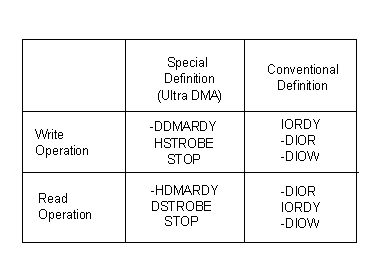
PIN    Signal   I/O    PIN   Signal    I/O

 01     -RESET     I      02     GND
 03      DD07     I/O     04     DD08       I/O
 05      DD06     I/O     06     DD09       I/O
 07      DD05     I/O     08     DD10       I/O
 09      DD04     I/O     10     DD11       I/O
 11      DD03     I/O     12     DD12       I/O
 13      DD02     I/O     14     DD13       I/O
 15      DD01     I/O     16     DD14       I/O
 17      DD00     I/O     18     DD15       I/O
 19      GND             (20)    KEY
 21      DMARQ     O      22     GND
 23     -DIOW *    I      24     GND
 25     -DIOR *    I      26     GND
 27      IORDY*    O      28     CSEL        I
 29     -DMACK     I      30     GND
 31      INTRQ     O      32    -HIOCS16     O
 33      DA01      I      34    -PDIAG      I/O
 35      DA00      I      36     DA02        I
 37     -CSO       I      38    -CS1         I
 39     -DASP     I/O     40     GND
Note:

ICRCE (Interface CRC error)
Bit 7 of Error Register is supported as Interface CRC Error bit. This bit
will be set if a CRC error has occurred on the data bus during an ULTRA-DMA transfer.
Check power mode
Check Power Mode command returns FFh to the sector count register
when the drive is in idle mode. This command does not support 80h
as the return value.
Sleep mode
During sleep mode the drive will be activated by any command, including,
but not limited to, a soft reset.
Hard reset
Hard reset response is identical to a soft reset reponse with the
following exception: in a hard reset, the drive goes through the
Master/Slave handshake to determine if a slave is present, in a soft
reset this handshake does not occur. In a hard reset the Master drive
looks at the DASP line to determine if it is asserted indicating a
Slave is present. The Master drive also checks the PDIAG line to
see if the Slave has passed its internal diagnostics.
Registers (primary channel addresses)
Address    Input register      Output register

1F0h        data                  data
1F1h        error                 features
1F2h        sector count          sector count
1F3h        sector number         sector number
            *LBA bits 0-7         *LBA bits 0-7
1F4h        cylinder low          cylinder low
            *LBA bits 8-15        *LBA bits 8-15
1F5h        cylinder high         cylinder high
            *LBA bits 16-23       *LBA bits 16-23
1F6h        drive/head            drive/head
            *LBA bits 24-27       *LBA bits 24-27
1F7h        status                command
3F6h        alternate status      device control
3F7h        drive address         not used
The host uses the register interface to communicate to and from
the drive. The registers are accessed through the host port
addresses shown. The host should not read or write any registers
when the Status Register BSY bit = 1.
Note: *Meaning of register contents when LBA addressing mode used.


| Product highlights |
Mechanical data |
| Product description |
Jumpers and configuration |
| Command descriptions |
Electrical interface specification |
