|
|
|
|
Component Elements
A texture is made up of components. Each of those components can contain several elements that determine the color, pattern, grain or bumps in the component.
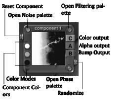
The Component window
You can have up to three components in your texture. As you activate components, a component window becomes active. Each window displays a preview of the component elements.
The Component window displays the selected component and its current attributes.
The three buttons on the Component window let you access the Noise palette, the Filtering palette and the Phase palette. The buttons along the right side of the window indicate the type of output produced by the component.
To activate a component:
1 Display the Deep Texture Editor.
2 Click the component selector in the top-left corner of the editor.
The selector lets you choose from 1, 2, or 3 components.
Color
The colors in a component determine its color scheme. Each component can have up to three colors. Colors can be chosen using the color picker or the Color dialog.
The color in a component is affected by the noise, filter and phase. You can create some very interesting patterns of color by modifying the noise. The color pattern created by the changes in the noise is applied directly to the final texture. So even if Color is the only output type for the component you'll still see a pattern in your final texture.
When the Color Output is selected for a component, only the color information is combined with the other components. Also, when you apply the texture to a material, the colors in the component contribute to the colors used in the Color channels of the material.
There are two color models you can use to create colors in the components: RGB and HLS. RGB combines red, green and blue to create color. HLS combines Hue, Lightness and Saturation values to create color. The method you choose depends on the final output of your Bryce scene. RGB works best for most types of output.
If the Color output is not active for a component, changing the colors or Color Blending Modes has no effect.
To activate Color output for a component:
1 Display the Deep Texture Editor.
2 In the desired component window, click the C button.
An output type is active when the button appears light gray.
To choose colors for a component:
1 Display the Deep Texture Editor.
2 In the desired component window, make sure the C button is active.
3 Click one of the color indicators along the left side of the component window and choose a color from the palette.
To mix colors for a component:
1 Display the Deep Texture Editor.
2 In the desired component window, make sure the C button is selected.
3 Option/Alt-click the one of the color indicators along the left side of the component window. The Color dialog appears.
4 Choose a color model by clicking one of the buttons along the bottom of the dialog.
5 Enter color values or adjust the sliders to mix a new color.
Color Blending Modes
There are several blending modes you can use to create a color scheme.
To choose a Color Blending mode:
1 Display the Deep Texture Editor.
2 In the desired component window, make sure the C button is active.
3 Click the triangle icon in the lower left corner of the window and choose a mode from the menu.
None
Red or Hue
When the RGB model is used, this mode outputs only red color values. When the HLS model is used, only Hue values are output.
This mode and the Green or Light, and Blue or Saturation mode are available so that you can separate color values among the components. For example, you could set each component to output one of the different color values.
Green or Light
When the RGB model is used, this mode outputs only green color values. When the HLS model is used, only Lightness values are output.
Blue or Saturation
When the RGB model is used, this mode outputs only blue color values. When the HLS model is used, only Saturation values are output.
Spline Interpol
This mode creates a blend between all the colors in the component.
Linear Interpol 2
This mode creates a linear blend between the first two colors selected for the component.
Linear Interpol 3
This mode creates a linear blend between all the colors in the component.
Randomized
In this mode the three colors are blended and then applied randomly throughout the component.
Earth Map
In this mode extra colors are generated according to the contours of the component's bump map. The three colors you selected for the component are applied to the middle range of the bump map. Blue is applied to the lowest bump values and white is applied to the highest values to simulate polar caps. Earth Map is excellent for creating planets.
Banded
In this mode colors are applied in bands. The bands are determined by color values. Colors with the lowest value (i.e. dark colors) are applied to the bands furthest from the center, colors with middle range values are applied next and colors with the highest values (i.e. bright colors) are applied closest to the center.
Perturbed
In this mode colors are applied in irregular patterns.
Interferences
In this mode the red, green and blue values of the first color in the component are used to create a repeating pattern around the contours of the component's noise.
Interpol + Interferences
This mode is a combination of Linear Interpolation and Interferences.
Altitude
In this mode a white layer is added above the colors at high altitudes. Any portion of the object below ground is automatically colored blue. Altitudes are based on the object's height.
Spline with Snow
This mode performs a spline interpolation of the colors in the component, but adds a white layer above the colors at high altitudes. Altitudes are based on the object's height.
Slope
In this mode the three colors are applied to the object depending on its slope.
Orient
In this mode the three colors are applied to the object according to its east-west orientation.
Noise
Noise is the background turbulence that creates the basis for texture patterns.
In audio terms you can think of noise as the background static that you hear on old recordings. Sound is layered on top of this noise to create music. Like in audio, you layer other functions on top of the noise in your texture to create the final pattern or look of your texture.
There are two ways of creating noise: the Noise palette or the Noise Editor.
The Noise palette can increase or decrease the amount of noise in any of the texture components. However, using the palette, you can only edit the existing noise.
To display the Noise palette:
1 Display the Deep Texture Editor.
2 Click the Noise button at the bottom of the editor. The Noise palette appears.
Click the Noise button in the top-left corner of on any of the component windows.
The Noise Editor is much more powerful than the Noise palette. It contains controls for creating noise from scratch.
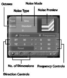
The Noise Editor lets you create noise and adjust its properties.
To display the Noise Editor:
1 Display the Deep Texture Editor.
2 Click the Noise button at the bottom of the editor. The Noise palette appears.
3 Click the top-left corner of the palette. The corner turns green as you pass your cursor over it.
Creating Noise
The Noise Editor is the tool you'll use to create noise with a component or combined texture. The noise creation process involves several steps:
- Choose the number of dimensions in the noise.
- Choose a Noise Type. This will give the basis for creating a noise pattern or grain.
- Adjust the frequency of the noise.
- Adjust the direction of the noise.
- Apply a modifier to your noise, by choosing a Noise Mode.
The following sections describe the various parts of the editor and how to use them in the noise creation process.
Noise Dimensions
Texture in Bryce can exist in 3D so your noise can have up to three dimensions. Noise dimensions determine which axes you can use to adjust the orientation and frequency of the noise.
It's easier to see the number of dimensions for your noise if you use a cube in the Noise Preview.
To choose the number of dimensions for your noise:
1 Display the Deep Texture Editor.
3 Click one of the dimension buttons at the bottom of the editor.
Noise Type
There are 27 different types of noise available in the Noise Editor. Random noise is the default (RND).
Each noise type provides you with a different basic pattern to start your texture. Some are more linear or geometric while others are more random.
More complex noise types require more rendering time. The time it takes to render the preview is a good indication of how long the final texture will take to render.
You should use the more complex noise types cautiously.
The best way of choosing a noise type is to apply a few to your component and see how they look. Remember that this noise is only the basis of the texture. You can still edit this noise using the other controls in the editor, so don't discard a noise type because it's not perfect. The other controls can help you fine-tune the noise.
To choose a noise type:
1 Display the Deep Texture Editor.
3 Click the Type field at the top of the editor and choose a noise type from the menu.
Noise Frequency
Noise Frequency determines how often the pattern within a texture repeats. Frequency is like scaling the noise. Higher frequencies decrease the scale of the noise so you can see the pattern more often. Lower frequencies increase the scale of the noise so the pattern repeats less often.
You can change noise frequency using the Frequency fields. The fields let you enter numerical values to adjust the noise frequency along the X, Y or Z axis. You can also adjust the values using the scroll arrows.
The number of dimensions in the noise determines how many axes you can use to adjust the frequency. For 1D noise you can only use the X axis. With 2D noise you can use both the X and Y axes. For 3D noise you can use all the axes.
If you try to adjust the Z axis frequency for a 2D noise, your changes will have no effect.
Adjusting the frequency can radically change the look of your noise. If you adjust the frequency in separate axes, you can achieve even more interesting effects.
To change the frequency of noise:
1 Display the Deep Texture Editor.
3 Drag over the X field in the Frequency area to set the noise frequency in the X axis.
Drag left to decrease the value or right to increase it.
4 Drag over the Y field in the Frequency area to set the noise frequency in the Y axis.
5 Drag over the Z field in the Frequency area to set the noise frequency in the Z axis.
You can also drag over the scroll arrows to speed up the increments.
Noise Orientation
Noise Orientation controls the direction of the noise. When you adjust the noise orientation, you change how the noise is laid out within the texture.
When you apply a texture, the direction of the noise within the texture remains constant regardless of the orientation of the object.
Since noise can exist in three dimensions, you adjust the direction of the noise in the X, Y, or Z axis.
The number of dimensions in the noise determines how many axes you can use to adjust the orientation. For 1D noise you can only use the X axis. With 2D noise you can use both the X and Y axes. For 3D noise you can use all the axes.
You can edit the noise orientation using the Direction numerical fields.The fields let you enter precise angles for noise orientation. You can also use the scroll arrows to set the angle in increments.
Changing noise orientation can dramatically change the look of your noise. You'll see just how different your noise can look when you rotate it along a single axis.
To change the orientation of noise:
1 Display the Deep Texture Editor.
3 Drag over the XY field in the Direction area to set the noise angle in the X and Y axes.
Drag left to decrease the value or right to increase it.
4 Drag over the YZ field in the Direction area to set the noise angle in the Y and Z axes.
You can also drag over the scroll arrows to speed up the increments.
Noise Octaves
Noise octaves are like musical octaves. In a musical scale, if you play F and then F an octave down, you're playing the same note, only it sounds lower. If you play both notes at the same time, the sound is more complex than if you played only one note. The same is true of noise. When you add an octave to noise it becomes more complex but the type of noise remains the same.
Increasing the octaves adds processing time to the component.
To change the number of octaves:
1 Display the Deep Texture Editor.
3 Drag over the octaves field at the top of the editor.
Noise Modes
Noise modes modify the octaves of a noise. As you add complexity by increasing the octaves, the Noise Modes let you modify the additional noise so that it produces different effects.
Many of the Noise modes use dark and light values to modify the existing noise. Also, you may not see the effects of the modes if the Octave is set to 0.
To choose a Noise Mode:
1 Display the Deep Texture Editor.
3 Click the Mode field at the top of the editor and choose a mode from the menu.
There are thirteen noise modes available:
Standard
This mode adds a new octave to the noise at half the frequency and twice the amplitude. This is the default mode.
Irregular
This mode adds a new octave to the noise at half the frequency and twice the amplitude. However, in this mode higher frequency noise is modified more than the rest. The end result is that more detail is added to the noise.
More Irregular
This mode works exactly like Irregular except that this mode is more intense.
Maximum
This mode uses the only the highest values, or lightest areas, to produce the modified noise.
Mulitfractal
In this mode lighter areas create higher contrast noise.
With Rotation
In this mode each additional octave is rotated. With Rotation mode it's easier to see linear noise types.
Minimum
This mode uses only the lowest values, or darkest areas, to produce the modified noise.
Multiply
In this mode all the values in the noise are multiplied together. The results is a darker noise.
Difference
In this mode all the values in the noise are evaluated. All the values that are equal create black areas. When the values are different, the lower value becomes darker. The more octaves you have in the noise, the darker the modified noise. Difference works even at 0 octaves.
Maximum 90
This mode repeats the noise at a 90° angle from its original orientation and combines the original and copy using only the highest values. This mode is good for creating woven patterns.
Minimum 90
This mode repeats the noise at a 90° angle from its original orientation and combines the original and copy using only the lowest values.
Auto-phased
This mode automatically introduces phase shifts into the noise.
Displaced Max
This mode creates a copy of the noise, displaces noise by a small amount, and then lightens any areas where the two overlap. This mode is good for creating stone textures.
Phase
Phase introduces turbulence into your noise. The phase displaces the grain or patterns within the noise. When you design the phase, you're creating a displacement map along which the noise will be modified.
You can control how the phase interacts with your noise using the Phase palette. You can design your phase using the Phase Editor.
The Phase palette controls the amplitude. The phase amplitude controls the intensity of the displacement. As the amplitude is increased, there is more interference with the original noise.
You won't have to increase the amplitude very much before you start seeing the phase pattern you designed interfere with the existing noise. In fact, it's probably a good idea to keep the phase amplitude low so that the phase pattern doesn't overwhelm the noise.
To display the Phase palette:
1 Display the Deep Texture Editor.
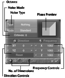
2 Click the Phase button at the bottom of the editor. The Phase palette appears.
The Phase Editor looks a lot like the Noise Editor. It has the same type of tools and they work exactly like they do in the Noise Editor. The difference is that you're using noise patterns, orientations, frequencies and modes to design how the basic Noise will be displaced.
Using the Phase Editor you can perform several functions:
- Create 1D, 2D, or 3D phase.
- Change the type of noise.
- Change the frequency of the phase.
- Change the orientation of the phase.
- Change the noise octaves.
- Change the noise modulations.
The Phase Editor lets you create noise to use as phase.
While the Phase Editor lets you create the noise pattern or grain within the phase, the Phase palette controls how that phase is applied to the component or the combined texture.
To display the Phase Editor:
1 Display the Deep Texture Editor.
2 Click the Phase button at the bottom of the editor. The Phase palette appears.
3 Click the top left corner of the palette. The corner turns green as you pass your cursor over it.
Creating Phase
Phase is designed using the Phase Editor. The phase creation process involves several steps:
- Choose the number of dimensions in the phase.
- Choose a noise type. This gives the basis for creating a phase pattern or grain.
- Adjust the frequency of the noise.
- Adjust the orientation of the noise.
- Apply a modifier to the noise by choosing a Noise Mode.
You'll notice that many of the steps for creating the phase are the same as those for creating noise. That's because you are creating noise. The difference is that instead of applying the noise to the texture, the noise you create for the phase is used to displace the existing noise.
The following sections describe the various parts of the editor and how to use them in the noise creation process.
Phase Dimensions
Just like noise, you can set the dimensions of the phase. The number of dimensions determines which noise axes will be displaced when you apply the phase. For example, if you apply a one-dimensional phase to a three-dimensional noise, only the X axis of the noise will be displaced.
Its easier to see the number of dimensions for your phase if you use a cube in the Phase Preview.
To choose the number of dimensions for your phase:
1 Display the Deep Texture Editor.
3 Click one of the dimension buttons at the bottom of the editor.
Phase Noise Type
There are 27 types of noise available in the Phase Editor. Random Noise is the default (RND).
Each noise type provides you with a different basic pattern for the phase. The noise types available in the Phase Editor are the same as those in the Noise Editor, so you can refer to "Noise Type" for more on noise types.
Phase Frequency
Phase frequency determines how often the pattern within the noise repeats. Frequency is like scaling the noise. Higher frequencies decrease the scale of the noise so you can see the pattern more often. Lower frequencies increase the scale of the noise so the pattern repeats less often.
You can change phase noise frequency using the Frequency numerical fields. The fields let you enter numerical values to adjust the noise frequency along the X, Y or Z axis. You can also adjust the values using the scroll arrows.
The number of dimensions in the phase determines how many axes you can use to adjust the noise frequency. For 1D phase you can only use the X axis. With 2D phase you can use both the X and Y axes. For 3D phase you can use all the axes.
Adjusting the frequency of the Phase noise disproportionately can have some very interesting effects on your noise.
To change the frequency of phase noise:
1 Display the Deep Texture Editor.
3 Drag over the X field in the Frequency area to set the phase noise frequency in the X axis.
Drag left to decrease the value or right to increase it.
4 Drag over the Y field in the Frequency area to set the Phase noise frequency in the Y axis.
5 Drag over the Z field in the Frequency area to set the Phase noise frequency in the Z axis.
You can also drag over the scroll arrows to speed up the increments.
Phase Noise Orientation
Phase noise orientation controls the direction of the noise within the phase.
The number of dimensions in the phase determines how many axes you can use to adjust the orientation.
You can edit the noise orientation using the Direction numerical fields.The fields let you enter precise angles for noise orientation. You can also use the scroll arrows to set the angle in increments.
Like frequency, changing the orientation of the phase noise in only one or two axes can create some very interesting results.
To change the orientation of phase noise:
1 Display the Deep Texture Editor.
3 Drag over the XY field in the Direction area to set the noise angle in the X and Y axes.
Drag left to decrease the value or right to increase it.
4 Drag over the YZ field in the Direction area to set the noise angle in the Y and Z axes.
You can also drag over the scroll arrows to speed up the increments.
Phase Noise Octaves
Phase noise octaves work exactly like the noise octaves. They introduce an extra level of complexity to the noise. Refer to "Noise Octaves" for more on octaves.
Phase Noise Modes
Phase noise modes work exactly like the noise modes. They modify the octaves of a noise. Refer to "Noise Modes" for more on octaves.
Filtering
The filter you apply to the noise in a component can change the entire look of the noise. The filter refines the noise so that it has more or less detail, increases its contrast, applies it only at high altitude or changes its spatial orientation. Whatever the change, the filter has a profound effect on the final look of your texture.
Filters are expressed as equations with variables. When the equation is applied to the noise, it changes some aspect of the noise. You can control how the equation affects the noise by changing the values of the variables.
The filter only affects the noise. The phase cannot be altered using a filter. The phase is blended with the noise.
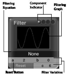
Filters are edited using the Filtering palette. The palette displays the current filter and provides tools for editing the filter graph.
The Filtering palette displays the current filter and provides tools for editing it.
To display the Filtering palette:
1 Display the Deep Texture Editor.
2 Click the Filtering button at the bottom of the editor.
Editing the Filter
Filters are equations which have variables. Each equation can have up to three variables labeled a, b and c. The values for each variable are displayed at the bottom of the palette. Generally, a controls the intensity of the filter effect while b controls the overall height. In some filters a and b may stand for other things.
There are two ways you can adjust a filter: by changing the variable values or by changing the shape of the graph (which automatically changes the variable values). The method you use depends on how much you know about a particular filter. If you're not sure what the filter does, change the graph-it's a much more intuitive way of working.
To edit the Filtering graph:
1 Display the Filtering palette.
2 Drag over the Filtering graph area. The shape of the graph changes as you drag.
Notice that the variables also changes as you move the graph.
To change variable values:
1 Display the Filtering palette.
2 Drag over the variable field you want to change. Drag left to reduce the value or right to increase it.
The shape of the graph changes as you adjust the values.
Choosing a Filter
Each filter available in the Filtering palette offers something unique. The best way of choosing which filter you want to use is to apply it to a component and see what happens.
To choose a filter:
1 Display the Deep Texture Editor.
2 Display the Filtering palette.
3 Click the Filtering Equation area and choose a filter from the menu.
There are fourteen filters available. The following sections describe the filters and gives you some idea of how to edit them.
None
This option deactivates the filter. No filtering is applied to the component.
Quantize
This filter works like a Posterize effect. When it's applied, gray values jump from one value to the next, creating a blocky stair-step type of effect.
In this filter a and b control the contrast and height, while c controls the number of levels between white and black.
Saw Wave
When the graph for this filter has only a small curve, it acts like a contrast filter. As it approaches the height limits (set by b), it bounces back on itself. This creates high-contrast breaks in the noise.
For color output use this filter to get areas of high-contrast alternating color.
When you set the value of a to a high number you'll get areas with a larger amount of noise.
Sine Wave-Sin (aX) + b
This filter creates noise that appears as large number of lines that are oriented in the same direction. Use this filter to generate wood grains.
The a variable controls the number of lines. Higher values create a better effect.
Absolute-Abs(aX + b)
This filter works like a Difference effect. When it's applied, you'll get more light areas in your noise and a higher level of detail in a bump map.
To get additional bump information using this filter, set a to 2 and b to -1.
XPower-(X PWR a) + b
This filter smooths out the darkest areas of your noise. However it has less effect on lighter areas and no effect on white.
Gaussian-(a(X + b))
This filter smooths out darker areas of your noise and makes lighter areas noisier. White areas become the noisiest.
Clip aX + b
Clip is probably the filter you'll use most. It's a contrast filter.
The a variable controls the contrast and b controls the overall brightness.
For a low contrast effect make the wave in the graph smaller. Decrease the value of a to reduce the size of the wave and increase b to move the wave up. Using this wave, all the values will be expressed as mid-gray.
For a high contrast effect, adjust the wave so that it hits both the top and bottom edges of the preview. Increase the value of a and make b negative to move the curve down.
To invert the colors in your noise, make a negative and increase b.
Altitude Minus Slope-Xb + a (Altitude-Slope)
This filter applies noise only at certain combinations of slope and altitude. When a is positive and b is negative, noise is applied at high altitudes and on flat surfaces.
When a is negative and b is positive, noise is applied at low altitudes and on steep slopes.
The Altitude Minus Slope filter works on the slope and altitude of an object in World Space.
Slope-X(a * Slope + b)
This filter applies noise based on an object's slope. Slope can range anywhere from flat and horizontal to steep and vertical. This is an excellent filter to use if you want to isolate a texture to vertical cliffs or flat surfaces.
In this filter a determines the steepness of the noise (-4 is flat, 4 is vertical). The b variable controls the starting point of the transition.
- To place noise on vertical surfaces make a=4 and b=2.
- To place noise on flat surfaces make a=-4 and b=1.5.
The Slope filter works on the slope of an object in World Space.
Altitude-X(a* Altitude + b)
This filter modulates the scale of the noise according to an object's altitude.
In this filter a determines how fast the noise is scaled by altitude. A lower value creates a gradual transition, while higher values create sharper transitions.
To apply noise at higher altitudes make sure a is positive. At high altitudes b controls the transition. The higher the transition, the lower the number. So, at high altitudes b should be a negative number.
To apply noise at lower altitude, reverse the variables so that a is negative and b is positive.
The Altitude filter works on the altitude of an object in World Space.
Orientation-X(a * Orientation + b)
This filter applies noise based on an object's east-west orientation.
Smooth Clip
This filter works exactly like the Clip filter. It's also a contrast filter, except that this filter smooths out the transitions between darks and grays.
The a variable controls the contrast and b controls the overall brightness.
Snow Puddles
This filter turns noise into snow patches. Snow is applied according to an object's slope and altitude.
The a variable controls how much the noise interferes with the smoothness of the snow. When a=0 the noise doesn't interfere at all so the snow is perfectly smooth. When the a value is higher, the snow starts looking like the noise.
The b variable shifts the altitude or snow level. It sets where the snow begins.
The c variable controls how steep an object has to be before the snow appears on its surface. The higher the number, the flatter an object has to be before snow appears on its surface.
 Corel Corporation http://www.corel.com Voice: (800) 772-6735 Fax: (716) 447-7366 www.corel.com/support |