
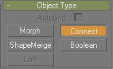
Select an object. > Create panel > Geometry > Compound Objects > Object Type rollout > Connect
Tab panels > Compounds tab > Connect Compound Object
The Connect compound object lets you connect two or more objects between "holes" in their surfaces. To do this, you delete faces in each object to create one or more holes in their surfaces, position them so that the holes face one another, and then apply Connect.
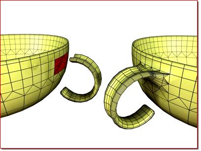
Left: Before connect
Right: After connect
Connect generates the best mapping coordinates it can for the bridges between the various holes in the meshes. While some ideal cases, such as a cylinder above another cylinder, can generate good UVW map interpolations, most cases cannot. You'll need to apply mapping to the bridge faces with a UVW map modifier.
Vertex colors, on the other hand, interpolate smoothly.
Procedures
To create a Connect object:
Create two mesh objects.
Delete faces on each to create holes where you want to bridge the objects.
Position the objects so that the normals of the deleted faces of one object point toward the normals of the deleted faces of the other object (assuming that deleted faces could have normals).
Select one of the objects. On the Create panel > Geometry > Compound Object Type rollout, click Connect.
Click the Pick Operand button, and then select the other object.
Faces are generated connecting the holes in the two objects.
Adjust the connection with the various options.
Example: To connect two cylinders:
Create a cylinder with a radius of 15 and a height of 30. Use the default settings for the remaining parameters.
Create a second cylinder centered on the first with a radius of 30, a height of 30, and 13 sides. (The fewer sides are to demonstrate the mesh interpolation in the connection.)
Move the first, narrower cylinder straight up along Z so its bottom cap is about 15 units above the top cap of the larger cylinder.
Convert both cylinders to editable meshes.
Delete the lower cap of the upper cylinder, and the upper cap of the bottom cylinder. (Hint: Go to Editable Mesh (Polygon) mode, select each end in turn, and then press the DELETE key.)
Exit sub-object mode, select the lower cylinder, and click Connect.
Click the Pick Operand button, and then click the upper cylinder.
New faces are created that span the openings in the two cylinders.
Example continued: To try out some options and create animation:
Go to the Modify panel and increase the Segments spinner to 5 or more.
As the segments increase, the connection becomes curved.
Set the Tension spinner to 0 to straighten the connecting surface, increase it to 1, and then return it to 0.5.
Try different combinations of the Bridge and Ends options.
Select the upper cylinder, turn on the Animate button, and apply various transforms at different frames.
Play the animation.
Notes:
You can use Connect on objects that have multiple sets of holes. Connect will do its best to match up the holes between the two objects.
The mapping coordinates assigned to the original two objects are maintained to the extent possible. You might find irregularities in the bridged area, depending on the complexity and difference between the two original sets of mapping coordinates and the types of geometry.
Interface
Pick Operand rollout
Pick Operand: Click this button to connect an additional operand to the original object.
For example, you might begin with a single object with two holes, and arrange two additional objects, each with one hole, outside of those holes. Click the Pick Operand button and select one of the objects, which is connected, and then click Pick Operand again and select the other object, which is connected. Both connected objects are added to the Operands list.
Reference/Copy/Move/Instance: Lets you specify how the operand is transferred to the compound object. It can be transferred either as a reference, a copy, an instance, or moved, in which case the original is not left behind.
Note: Connect works only with objects that are capable of being converted into Editable Meshes, Editable Patches, or Editable Polys.
Parameters rollout
Operands group
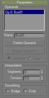
Operands list: Displays the current operands. Select an operand to rename, delete or extract by clicking it in this list.
Name: Renames a selected operand. Type in a new name, and then press TAB or ENTER.
Delete Operand: Deletes a selected operand from the list.
Extract Operand: Extracts a copy or an instance of the selected operand. Choose an operand in the list to enable this button.
Note: This button is available only in the Modify panel. You can't extract an operand while in the Create panel.
Instance/Copy: Lets you specify how the operand is extracted: as either an instance or a copy.
Interpolation group
Segments: Sets the number of segments in the connecting bridge.
Tension: Controls the curvature in the connecting bridge. A value of 0 provides no curvature, while higher values create curves that attempt to more smoothly match the surface normals on either end of the connecting bridge. This spinner has no apparent effect when Segments is set to 0.
Smoothing group
Bridge: Applies smoothing between the faces in the connecting bridge.
Ends: Applies smoothing between the faces that border the old and new surfaces of the connecting bridge and the original objects. When turned off, The software assigns a new material ID number to the bridge. The new number is one higher than the highest ID number assigned to either of the original objects. When on, the ID number is taken from one of the original objects.
Note: If both Bridge and Ends are on, but the original objects contain no smoothing groups, then smoothing is assigned to the bridge and to the faces bordering the bridge.
Display/Update rollout
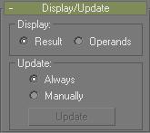
Display group
Determines whether the shape operands are displayed.
Result: Displays the result of the operation.
Operands: Displays the operands.
Update group
These options determine when the projection for the compound object is recalculated. Because complex compound objects can slow performance, you can use these options to avoid constant calculation.
Always: The object is updated constantly.
Manually: Activates the Update button for manual recalculation.
Update: Recalculates the projection.