
Select an object. > Modify panel > Modifier List > UV Coordinate Modifiers > UVW Map
Select an object. > Modifiers menu > UV Coordinates > UVW Map
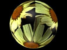
Mapping a sphere and a box
By applying mapping coordinates to an object, the UVW Map modifier controls how mapped materials appear on the surface of an object. Mapping coordinates specify how bitmaps are projected onto an object. The UVW coordinate system is similar to the XYZ coordinate system. The U and V axes of a bitmap correspond to the X and Y axes. The W-axis corresponds to the Z-axis. A bitmap's coordinate system can be switched in the Material Editor to VW or WU, in which case the bitmap is rotated and projected so that it is perpendicular to the surface.
Primitive objects, like spheres and boxes, can generate their own mapping coordinates, as can loft objects. Scanned, imported, or hand-constructed polygonal or patch models do not have mapping coordinates until a UVW Map modifier is applied. If you apply a UVW Map modifier to an object with built-in mapping coordinates, the applied coordinates take precedence if map channel 1 in the UVW Map modifier is used. The Generate Mapping Coordinates option, available during the creation of primitives, uses map channel 1 by default.
You use the UVW Map modifier to:
Apply one of the seven types of mapping coordinates to an object on a specified map channel. A diffuse map on map channel 1 and a bump map on map channel 2 can have different mapping coordinates and can be controlled separately by using two UVW Map modifiers in the modifier stack
Transform the mapping gizmo to adjust map placement. Objects with built-in mapping coordinates lack a gizmo
Apply mapping coordinates to an object with no mapping coordinates, an imported mesh, for example
Apply mapping at the sub-object level
You can control the type of mapping coordinates and the placement of the mapping gizmo for each bitmap in a material that uses multiple bitmaps by assigning explicit map channels to the bitmaps. In the Material Editor you assign each map a different channel number, then you add multiple UVW Map modifiers to the object's modifier stack, each UVW Map modifier is set to a different map channel. To change the type of mapping or gizmo placement for a particular bitmap, you select one of the UVW Map modifiers in the modifier stack and change the parameters. You can change the name of a UVW Map modifier in the Edit Modifier Stack dialog to correlate the modifier to the bitmap.
Changing a map's location by moving the gizmo
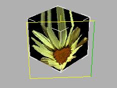
The UVW Map gizmo projects mapping coordinates onto an object. You can position, rotate, or scale a gizmo to adjust map coordinates on an object; gizmos can also be animated. Gizmo transformations remain in effect if you select a new map type. If a spherical mapping gizmo is scaled, and you switch to planar mapping, then the planar mapping gizmo is also scaled.
For planar, spherical, cylindrical and shrink wrap maps, a short yellow line indicates the top of the map. The green edge of the gizmo indicates the right side of the map. On a spherical or cylindrical map the green edge is the seam where the left and right edge meet. Gizmo must be selected in the modifier display hierarchy to display the gizmo.
Moving the gizmo changes the center of projection and affects all types of mapping. Rotating the gizmo changes the orientation of the map, which affects all types of mapping. Uniform scaling does not affect spherical or shrink-wrap mapping. Non uniform scaling affects all types of mapping.
If you scale a gizmo smaller than the geometry, then a tiling effect is created, unless scaling has no effect on the map type in use. Tiling based on gizmo size is in addition to tiling values set in the Material Editor Coordinates rollout for the map or the UVW Map modifier tile controls.
The UVW Map modifier has graphic manipulators to help you adjust the UV length, width, and tiling.
 Manipulators are visible and usable while the Select and Manipulate button is turned on. This button is on the default main toolbar. When you move the mouse over a manipulator, the manipulator turns red to show that dragging or clicking it will have an effect. Also, a tooltip appears, showing the object name, the parameter, and its value.
For more information on using the UVW Map manipulators, see the Procedures section in this topic.
UV width-length manipulators: In a viewport, drag the edges of the UVW Map gizmo to change the width or height.
UV tiling manipulators: In a viewport, drag the small circle next to the U edge or V edge to adjust the tiling in that dimension.
Use the UVW Tile controls if you want a map to repeat. Tiled maps are useful for bricks on a wall, or tiles on a floor. Rather than creating one large map, seamless maps can be tiled to surface a large area without visible seams, to give the illusion of a large map.
To apply the UVW map modifier:
Assign a mapped material to an object.
 On the Modify panel, choose UV Coordinate Modifiers > UVW Map from the Modifier List.
Adjust the mapping parameters.
By default, the UVW Map modifier uses planar mapping on map channel 1. You can change the type of mapping and the map channel to suit your needs. There are seven types of mapping coordinates, ninety-nine map channels, tiling controls, and controls to size and orient the mapping gizmo in the UVW Map modifier.
Note: If a UVW Map modifier is applied to multiple objects, the UVW Map gizmo is defined by the selection, and the mapping that results is applied to all the objects.
To transform a UVW Map gizmo:
On the Modify panel, choose UV Coordinate Modifiers > UVW Map from the Modifier List.
In the stack display, choose the Gizmo sub-object level.
The gizmo changes to a yellow color, with one green edge.
Move, scale, or rotate the gizmo in the viewports, or use the Length and Width controls in the UVW Map modifier.
Transforming the map gizmo shifts the bitmap, allowing you to orient and move the map on the object's surface.
To use manipulators to control the width and length:
On the Modify panel, choose the UVW Map modifier in the stack display.
You can also be at the Gizmo level of the modifier.
On the default main toolbar, click to turn on Select And Manipulate.
The UVW Map modifier's gizmo turns green, showing it is now a manipulator. Also, two small circles appear next to two of the gizmo's edges.
Drag an edge of the gizmo to adjust the width or length.
A tooltip shows the new width or length value.
To use manipulators to control tiling:
On the Modify panel, choose the UVW Map modifier in the stack display.
You can also be at the Gizmo level of the modifier.
On the default main toolbar, click to turn on Select And Manipulate.
The UVW Map modifier's gizmo turns green, showing it is now a manipulator. Also, two small circles appear next to two of the gizmo's edges.
Drag one of the circles to adjust tiling in the U or V dimension.
A tooltip shows which dimension you are adjusting, and the new tiling value in that dimension.
Modifier Stack
Gizmo Level: Enables gizmo transformations. Turn on and then move, scale, and rotate the gizmo in the viewports to position the map. In the Material Editor, you turn on the Show Map in Viewport option to make the map visible in a shaded viewport, the map moves on the surface of the object as you transform the gizmo.
Mapping group
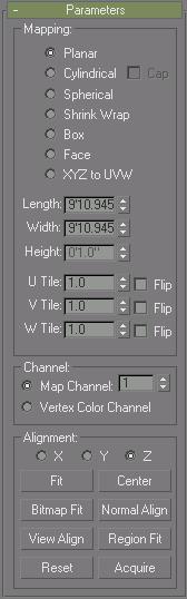
Determines the type of mapping coordinates used. Different kinds of mapping are distinguished by how the map is geometrically projected onto the object and how the projection interacts with the object's surfaces.
Planar map projection
Planar: Projects the map from a single plane flat against the object, somewhat like projecting a slide.
Planar projection is useful when only one side of an object needs to be mapped. It is also useful for obliquely mapping multiple sides, and for mapping two sides of a symmetrical object.
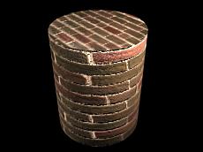
Cylindrical map projection
Cylindrical: projects the map from a cylinder, wrapping it around an object. Seams where the edges of the bitmap meet are visible unless a seamless map is used. Cylindrical projection is useful for objects that are roughly cylindrical in shape.
Cap: Applies planar mapping coordinates to the caps of the cylinder.
Note: If the ends of the object geometry are not at right angles to the sides, the Cap projection bleeds onto the sides of the object.
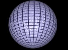
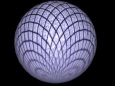
Spherical map projection
Spherical: Surrounds the object by projecting the map from a sphere. You see a seam and mapping singularities at the top and bottom of the sphere where the bitmap edges meet at the sphere's poles. Spherical mapping is useful for objects that are roughly spherical in shape.
Shrink-wrap projection
Shrink Wrap: Uses spherical mapping, but truncates the corners of the map and joins them all at a single pole, creating only one singularity. Shrink-wrap mapping is useful when you want to hide the mapping singularity.
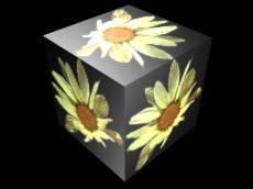
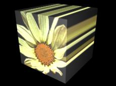
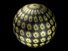
Box projection (shown on a box and on a sphere)
Box: Projects the map from the six sides of a box. Each side projects as a planar map, and the effect on the surface depends on the surface normal. Each face is mapped from the closest box surface whose normal most closely parallels its own normal.
Face projection
Face: Applies a copy of the map to every face of an object. Pairs of faces sharing a hidden edge are mapped with the full rectangular map. Single faces with no hidden edge are mapped with a triangular portion of the map.
XYZ to UVW: Maps 3D procedural coordinates to UVW coordinates.
Length, Width, Height: Specify the dimensions of the UVW Map gizmo. The default scale of the mapping icon is defined by the largest dimension of the object when you apply the modifier. You can animate the projection at the gizmo level. Note the following about these spinners:
The dimensions are based on a bounding box of the gizmo.
The Height dimension is unavailable for the Planar gizmo: It does not have depth. Likewise, the dimensions for Cylindrical, Spherical, and Shrink Wrap mapping all display the dimensions of their bounding box and not their radii. No dimensions are available for the Face map: Each face on the geometry contains the entire map.
The dimensions essentially become scale factors rather than measurements. You can reset the values to dimensions by clicking the Fit or Reset buttons, which will lose the original non-uniform scaling.
U Tile, V Tile, W Tile: Let you specify the dimensions of the UVW map, for tiling the image. These are floating-point values; you can animate these values to displace the map's tiling over time.
Flip: Reverses the image about the given axis.
Channel group
Each object can have up to 99 UVW mapping coordinate channels. The default mapping (from the Generate Mapping Coordinates toggle) is always channel 1. The UVW Map modifier can send coordinates to any channel. This lets you have many different sets of coordinates on the same face simultaneously.
Map Channel: Provides the mapping coordinates that are assigned when you turn on Generate Mapping Coordinates in an object's creation parameters. The UVW Map modifier defaults to channel 1, so mapping behaves in the default fashion unless you explicitly change to another channel. Default=1. Range=1 to 99
To use the additional channels, you must not only choose a channel in the UVW Map modifier, but also assign an explicit map channel at the map level of the material assigned to the object. You can use many UVW Map modifiers in the modifier stack, each one controlling the mapping coordinates of different maps in a material.
Vertex Color Channel: Define the channel as a vertex color channel by choosing this option. Be sure to match any material mapping in the coordinates rollout to be Vertex Color as well, or by using the Assign Vertex Color utility.
The Map channels are accessed in various places in gmax, as follows:
Generate Mapping Coords: This check box, in the creation parameters of most objects, assigns UVW Map channel 1 when turned on.
UVW Map Modifier: Contains options for channels 1 through 99. This lets you specify which UVW coordinates are used by this UVW Map modifier. The modifier stack can pass these channels simultaneously for any face.
UVW Xform and Unwrap UVWs: These two modifiers also contain Channel option buttons.
Material Editor Channel Assignment: You assign the channel to be used by a map in the Coordinates rollout at the map level in the Material Editor.
The assignment varies depending on the type of map:
2D Maps: In the Mapping list for the Texture option, you can choose Explicit Map channel, Vertex Color Channel, Planar from Object XYZ, or Planar from World XYZ.
3D Maps: At the top of the Coordinates rollout, there is a Source list where you can choose an Explicit Map Channel, Vertex Color Channel, Object XYZ, or World XYZ. Use the Map Channel spinner to define the channel number.
Alignment group
X/Y/Z: Select one of these to flip the alignment of the mapping gizmo. Each specifies which axis of the gizmo is aligned with the local Z-axis of the object.
Note: These options aren't the same as the Flip check boxes beside the U/V/W Tile spinners. The Alignment option buttons actually flip the gizmo orientation, while the Flip check boxes flip an assigned map's orientation.
Fit: Fits the gizmo to the extents of the object and centers it so that it's locked to the object's extents.
Center: Moves the gizmo so that its center coincides with the center of the object.
Bitmap Fit: Displays the standard bitmap file browser so that you can pick an image. For planar mappings, the map icon is set to the aspect ratio of the image. For cylindrical mapping, the height (rather than the radius of the gizmo) is scaled to match the bitmap. For best results, first use the Fit button to match the radii of the object and gizmo, and then use Bitmap Fit.
Normal Align: Click and drag on the surface of the object to which the modifier is applied. The origin of the gizmo is placed at the point on the surface where the mouse is pointing; the XY plane of the gizmo is aligned to the face. The X-axis of the gizmo lies in the object's XY plane.
Normal Align respects smoothing groups and uses the interpolated normal based on face smoothing. As a result, you can orient the mapping icon to any part of the surface, rather than having it "snap" to face normals.
View Align: Reorients the mapping gizmo to face the active viewport. The size of the icon is unchanged.
Region Fit: Activates a mode in which you can drag in the viewports to define the region of the mapping gizmo . The orientation of the gizmo is not affected.
Reset: Deletes the current controller controlling the gizmo and plugs in a new one initialized using the Fit function. Any animation to the gizmo is lost. However, like all the alignment options, Reset is undoable.
Acquire: Effectively copies the UVW coordinates from other objects When you pick an object from which you want to acquire UVWs , a dialog prompts you whether the acquire should be done in an absolute or relative fashion.
If you choose Absolute, the acquired mapping gizmo is positioned exactly on top of the mapping gizmo you pick. If you choose Relative, the acquired mapping gizmo is positioned over the selected object.
Mapping Selection Sets or Grouped Objects
You can apply one UVW Map modifier to a selection of objects. One large mapping gizmo will encompass the entire selection unless the Use Pivot Points option is turned on in the modifiers rollout before applying the UVW Map modifier. If the Use Pivot Points option is used then each object is encompassed with its own mapping gizmo.
If any of the objects in the selection has had its pivot point shifted in the Hierarchy > Pivot panel, and you use the Use Pivot Points option with the UVW Map modifier, then the mapping gizmos are centered to the pivot points rather than the object center and the mapping may be tricky to position the way you want.