Connecting a Video Deck — Component Signal
An optional component video deck connection requires the following:
 | |
Two Avid Mojo DNA component video cables
|
| |
A video deck with component inputs and outputs
|
To connect a deck using component signals:
| 1. | |
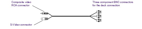
Locate a component video cable (see The following figure).
|
There are three BNC connectors on one end of the cable; the other end
has an RCA connector and an S-Video connector.
| 2. | |
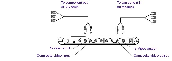
Attach the RCA and S-Video end of the cable to the Avid Mojo DNA
inputs as follows (see The following figure):
|
| a. | |
Connect the RCA connector to the yellow Composite video input
connector on the Avid Mojo DNA.
|
| b. | |
Connect the S-Video connector to the S-Video input connector on
the Avid Mojo DNA.
|
| 3. | |
Attach the other end of the component cable (with the three BNC
connectors) to Component output of your video deck as follows:
|
| a. | |
Connect the BNC attached to the green wire to the component
output connector labeled Y.
|
| b. | |
Connect the BNC attached to the red wire to the component output
connector labeled R-Y.
|
| c. | |
Connect the BNC attached to the blue wire to the component
output connector labeled B-Y.
|
| a. | |
Connect the RCA connector to the yellow Composite video output
connector on the Avid Mojo DNA.
|
| b. | |
Connect the S-Video connector to the S-Video output connector on
the Avid Mojo DNA.
|
| 5. | |
Attach the other end of the component cable (with the three BNC
connectors) to Component input of your video deck as follows:
|
| a. | |
Connect the BNC attached to the green wire to the component
input connector labeled Y.
|
| b. | |
Connect the BNC attached to the red wire to the component input
connector labeled R-Y.
|
| c. | |
Connect the BNC attached to the blue wire to the component input
connector labeled B-Y.
|
 | |
Make sure you terminate the input signal if your video deck supports
passthrough. See the documentation that is provided with your video deck.
|