
Create panel > Helpers > Standard > Object Type rollout > Grid
Tab panels > Helpers tab > Grid Object
The grid, also called "User Grid" or "Custom Grid", is a 2D parametric object with adjustments for overall size and grid spacing. You can move and orient user grids anywhere in world space.
You can create any number of grid objects in your scene. You name them when you create them and save them with the scene. You can delete them at any time.
Like other objects you create in the software, grid objects are placed on the grid of the current viewport. By default, this is a plane of the home grid, but it can also be another activated grid object.
Note: You can use AutoGrid to create a temporary or permanent user grid off the surface of any object. See AutoGrid for more information.
You can use the grid object as a construction plane on all three orthographic planes in both directions. Here's how it works:
In the Parameters rollout of each grid object is a Display group box with three option buttons: XY Plane, YZ Plane, and ZX Plane. These determine which of the three planes of the grid object is displayed in the viewport.
When you activate a grid object, the displayed plane is the construction plane for all viewports. When you create a grid viewport, you can choose from one of six orthographic views (Front, Top, Left, and so on), or you can choose a special "Display Planes" grid viewport. (When you press the "G" key to create a grid viewport, the Display Planes type becomes the default.) The Display Planes type of grid viewport always displays the plane chosen by the three option buttons under Display. Thus, as you switch between XY Plane, YZ Plane, and ZX Plane, the view through the grid viewport switches accordingly, and objects created in that viewport are created on the displayed plane.
When you right-click on a viewport label (or go to the Layout page of the Viewport Configuration dialog), you can choose six additional types of grid viewports, based on the six orthographic views. These are available by a cascading Grid menu that provides Left, Right, Front, Back, Top, Bottom, and Display Planes. Each of the orthographic directions is local to the grid object, regardless of its orientation in the scene.
When you choose a specific orthographic grid viewport (as opposed to the Display Planes viewport), the construction of objects in that viewport is on the plane specified in the viewport title regardless of the displayed plane of the grid object.
You can create more than one viewport based on the same grid object, with each using a different plane. For example, you can have a Grid (Front) viewport and a Grid (Top) viewport, as well as a Grid (Display Planes) viewport.
When you deactivate a grid object, its remaining viewports show the assigned orthographic view. Thus, a Grid (Front) viewport becomes a Front viewport, for example. A Grid (Display Planes) viewport always reverts to a Top view, regardless of the currently displayed plane.
As a rule, don't use scaling to resize a grid object. Scaling enlarges or reduces the apparent size of the grid object but has no effect on grid spacing. A sphere 20 units in radius created on a grid object appears smaller than another 20-unit sphere created on a scaled-up version of the same grid.
If you want to change the actual size of the grid object, select it and go to the Modify panel > Parameters rollout > Grid Size group box, and change the Length and Width settings.
Grid tools are spread throughout the interface of the software.
In the Views menu, under Grids, are the commands to activate home and user grids.
The same tools are available with a right-click anywhere in the viewport.
Choose Customize menu > Grid and Snap Settings to display the Grid and Snap Settings dialog. Two tabs are devoted to Grid tools, one for home, another for user grids. You can change parameters of any active grid using the Modify panel.
To create a grid object:

 Click Create panel > Helpers > Standard > Object Type rollout > Grid.
A Parameters rollout appears on the Create panel.
In a viewport, drag a rectangle and release the mouse button. This creates and selects a grid object, which appears in white wireframe, divided into four quadrants with coordinate axes at the center.
While the newly created grid object is still selected, you can change its settings on the Parameters rollout.
You can also create a grid object during object creation. Turn on AutoGrid, then press ALT during object creation. A grid is created at the same time as the object and remains displayed and active. See AutoGrid for more information.
To activate a grid object:
A grid object requires activation before use. Standard selection doesn't activate it unless you turn on the option to do so (see User Grids).
Only one grid can be active for construction at a time, whether it's the home grid or a grid object. Activating a user grid "deactivates" the home grid.
Activating a grid object enables options to reactivate the home grid on the Views menu > Grids submenu and the Quad menu.
If you have more than one grid object in your scene, you have to activate each one separately. Select the grid object you want to make active and follow the same procedure. Activating another grid object deactivates the current one.
Select a grid object.
Do one of the following:
From the Views menu, choose Grids > Activate Grid Object.
Right-click the selected grid object and choose Activate Grid > Selected.
The grid object changes to show its internal grid structure. Except for its main axes, the home grid disappears in all viewports.
To return to the home grid:
Do one of the the following:
From the Views menu, choose Grids > Activate Home Grid.
Right-click the selected grid object and choose Activate Home Grid from the Viewport Properties menu.
This deactivates the grid object and returns the home grid in all views.
If you delete an activated grid object, the home grid also reactivates.
You can assign a keyboard shortcut to Activate Home Grid in the Keyboard panel of the Customize User Interface dialog. This is useful if you need to move back and forth between different grids.
To use a grid object as construction plane:
When activated, a grid object replaces the home grid as the frame of reference for creating objects.
An activated grid object creates a true plane in 3D space. No matter how small an activated grid object appears on screen, its XY plane is effectively infinite, just as if it were the XY plane of the home grid.
Activate the grid object.
Create any category of object from the Create command panel.
The software creates the object directly on the plane of the grid object, with the object's Z axis perpendicular to the plane.
See Align for details on aligning objects and grids.
Like other objects in the software you can move and rotate grid objects freely using standard transformation methods. These transforms, along with alignment, are essential in positioning a construction plane in 3D space.
To nudge a grid object up or down:
Activate the grid object.
Press the + or - keys on the numeric keypad to move the grid object up or down.
The Grid Nudge Distance is controlled in the Viewports panel of the Preferences dialog.
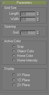
Grid Size group
Sets the overall size of the grid object. This size determines the extents of a viewport set to the grid object. It doesn't affect the useful limits of the grid, which extend infinitely.
Length/Width: Specifies the length and width of the grid.
Grid Spacing group
Grid: Specifies the size of the smallest square in the visible grid. This setting appears on the status line when the grid is activated.
Note: You can set Grid Spacing when a grid is selected, but you won't see the grid spacing until the grid is activated.
Active Color group
Determines the color used to draw the grid in viewports when it's not selected.
Gray: The active grid object is two shades of gray.
Object Color: The main grid lines use the assigned object color, while the secondary lines use a lighter intensity.
Home Color: The grid object uses whatever custom color has been assigned the home grid in the Customize User Interface Dialog.
Home Intensity: The grid object uses the same Grid Intensity settings as those assigned to the home grid in the Customize User Interface Dialog.
Display group
XY Plane, YZ Plane, ZX Plane: Determines which of the three planes of the grid object are displayed in the viewport.