
Select an editable poly object. > Modify panel > Selection rollout > Vertex
Select an editable poly object. > Modify panel > Modify Stack display > Editable Poly rollout > Vertex
Select an editable poly object. > Quad menu > Tools 1 quadrant > Sub-Objects sub-menu > Vertex
Vertices are points in space: they define the structure of other sub-objects that make up the poly. When vertices are moved or edited, the geometry they form is affected as well. Vertices can also exist independently; such isolated vertices can be used to construct other geometry.
When in Editable Poly (Vertex) mode, you can select single and multiple vertices and move them using standard methods. This topic covers the Edit Geometry rollout; for other controls, see Editable Poly.
To select vertices by color:
In the Surface Properties rollout, under Select Vertices By, click the color swatch, and specify the color of vertex you want in the Color Selector.
Specify ranges in the RGB Range spinners. This lets you select vertices that are close to the specified color, but don't match exactly.
Click the Select button.
All vertices matching the color, or within the RGB range, are selected.
You can add to the selection by holding CTRL when you press the Select button, and you can subtract from the selection by holding the ALT key.
Tip: You can select all vertices of the same color by first selecting the vertex you want matched, dragging a copy of the Edit Color swatch to the Existing Color swatch, and then clicking the Select button. (If you want an exact match, be sure to set the RGB Range spinners to 0 first.)
Interface
Selection rollout
See Editable Poly for information on the Selection rollout settings.
Soft Selection rollout
Soft Selection controls affect the action of sub-object Move, Rotate, and Scale functions. When these are on, the program applies a spline curve deformation to unselected vertices surrounding the transformed selected sub-object. This provides a magnet-like effect with a sphere of influence around the transformation.
For more information, see Soft Selection rollout.
Edit Geometry rollout
Create: Lets you add vertices to a single selected poly object. After selecting the object and clicking Create, click anywhere in space to add free-floating vertices to the object. The new vertices are placed on the active construction plane.
Delete: Deletes selected vertices and any attached polygons.
Attach: Lets you attach another object in the scene to the selected editable poly. You can attach any type of object, including splines and patch objects. Attaching a non-mesh object converts it to editable-poly format. Click the object you want to attach to the currently selected poly object.
For further details, see Attach.
Detach: Detaches the selected vertices and all attached polygons from the poly object, creating a separate object or element. The Detach As Clone option copies the polygons rather than moving them.
You're prompted to enter a name for the new object. Detached polygons leave a hole in the original object when you move them to a new position.
Break: Creates a new vertex for each polygon attached to selected vertices, allowing the polygon corners to be moved away from each other where they were once joined at the original vertex. If a vertex is isolated or used by only one polygon, it is unaffected.
Collapse: Collapses selected vertices into an averaged vertex.
Chamfer: Click this button and then drag vertices in the active object. The Chamfer spinner updates to indicate the chamfer amount as you drag.
Chamfer button: Click this button, and then drag vertices in the active object. The Chamfer Amount spinner updates to indicate the chamfer amount as you drag.
If you drag one or more selected vertices, all selected vertices are chamfered identically. If you drag an unselected vertex, any selected vertices are first deselected.
A vertex chamfer "chops off" the selected vertices, creating a new face connecting new points on all visible edges leading to the original vertex. These new points are exactly <chamfer amount> distance from the original vertex along each of these edges. New chamfer faces are created with the material ID of one of the neighboring faces (picked at random) and a smoothing group which is an intersection of all neighboring smoothing groups.
For example, if you chamfer one corner of a box, the single corner vertex is replaced by 3 vertices moving along the three visible edges that lead to the corner. Outside faces are rearranged and split to use these three new vertices, and there's a new triangle created at the corner.
Slice Plane: Creates a gizmo for a slice plane that can be positioned and rotated where you want to slice the edges. Also enables the Slice button.
Reset Plane: When in Slice Plane mode, use this button to return to the previous plane.
Slice: Performs the slice operation at the location of the slice plane. The Slice button is available only when the Slice Plane button is highlighted. This tool slices the poly just like the Slice modifier in "Operate On: Polygon" mode.
Cut: Lets you cut from vertex to vertex.
Split: When on, the Slice and Cut operations create double sets of vertices at the points where the edges are divided. This lets you easily delete the new polygons to create holes, or animate the new polygons as separate elements.
Weld group
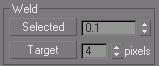
Tip: Welding only works on border vertices. It is not possible to weld arbitrary points together as can be done in Editable Mesh since this would create illegal polymeshes. For conditions when welding is not allowed, Collapse can be used in place of Weld.
Selected: Welds selected vertices that fall within the tolerance specified in the spinner. All line segments become connected to the resulting single vertex.
Target: Allows you to select a vertex and weld it to a target vertex. When positioned over a vertex, the cursor changes to a + cursor. Click and move the mouse and a dashed line appears from the vertex with an arrow cursor at the other end of the line. Position the cursor over another vertex and when the + cursor appears again, click to weld the vertices.
The pixels spinner to the right of the Target button sets the maximum distance in screen pixels between the mouse cursor and the target vertex.
Make Planar: Forces all selected vertices to become coplanar. The plane's normal is the average surface normal of all polygons attached to the selected vertices.
View Align: Aligns selected vertices to the plane of the active viewport. In the case of orthographic viewports, this is the same effect as aligning to the construction grid when the home grid is active. When aligning to a Perspective viewport (including camera and light views), the vertices are reoriented to be aligned to a plane that is parallel to the camera's viewing plane. (Perspective viewports have invisible camera planes.) In these cases, the selection of vertices is not translated but only rotated.
Grid Align: Aligns the selected vertices to the current construction plane. The current plane is specified by the active viewport in the case of the home grid. When using a grid object, the current plane is the active grid object.
Remove Isolated Vertices: Deletes all isolated vertices in the object, regardless of the current selection.
Subdivide rollout

MeshSmooth group
These controls provide explicit MeshSmooth NURMS subdivision for object and sub-object smoothing using the MeshSmooth modifier.
Smoothness: Determines how sharp a corner must be before polygons are added to smooth it. Smoothness is calculated as the average angle of all edges connected to a vertex. A value of 0.0 prevents the creation of any polygons. A value of 1.0 adds polygons to all vertices even if they lie on a plane.
Separate by Smoothing Groups: Prevents the creation of new polygons at edges between polygons that don't share at least one smoothing group.
Separate by Materials: Prevents the creation of new polygons for edges between polygons that do not share Material IDs.
Tessellate group
Use these controls to tessellate (subdivide) selected polygons. Tessellation is useful for increasing local mesh density while modeling. You can subdivide any selection of polygons. Two tessellation methods are available:
Tessellate: Tessellates selected polygons based on the Edge, Face-Center, and Tension (spinner) controls.
Edge: Inserts vertices in the middle of each edge and draws lines connecting those vertices. The number of polygons created will equal the number of sides of the original polygon.
Face: Adds a vertex to the center of each polygon and draws connecting lines from that vertex to the original vertices. The number of polygons created will equal the number of sides of the original polygon.
Tension: (Active only when Tessellate by Edge is active.) This spinner, below the Tessellate button, lets you increase or decrease the Edge tension value. A negative value pulls vertices inward from their plane, resulting in a concave effect. A positive value pulls vertices outward from their plane, resulting in a rounding effect.
Surface Properties rollout

These controls let you set the color for vertices.
Weight: Sets the weight of selected edges. Increasing an edge weight tends to push the smoothed result away.
Edit Vertex Colors group
Use these controls to assign the color, and illumination color (shading) of selected vertices.
Color: Click the color swatch to change the color of selected vertices.
Illumination: Click the color swatch to change the illumination color of selected vertices. This lets you change the illumination without changing the vertex's color.
Alpha: Lets you assign an alpha (transparency) value to selected vertices.
The spinner value is a percentage; zero is completely transparent and 100 is completely opaque.
Select Vertices By group
Color and Illumination radio buttons: These buttons determine whether to select vertices by vertex color values or vertex illumination values.
Color Swatch: Displays the Color Selector, where you can specify a color to match.
Select: Depending on which radio button is selected, selects all vertices whose vertex color or illumination values either match the color swatch, or are within the range specified by the RGB spinners.
Range: Specifies a range for the color match. All three RGB values in the vertex color or illumination must either match the color specified by the Color swatch in Select By Vertex Color, or be within plus or minus the values in the Range spinners. Default=10.