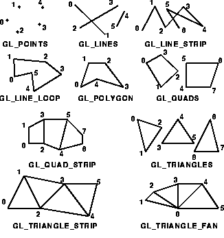
The programmer is provided the following primitives for use in constructing geometric objects.

Each geometric object is described by a set of vertices and the type of the primitive to be drawn. Whether and how the vertices are connected is determined by the primitive type. For a more detailed discussion of these primitives, refer to Section 2.6.1 Begin and End Objects of the OpenGL Specification.
With OpenGL, all geometric objects are ultimately described as an ordered set of vertices. The command glVertex*() is used to specify a vertex. Here are some example uses of glVertex*():
	glVertex2s(1, 2);
	glVertex3d(0.0, 0.0, 3.1415926535898);
	glVertex4f(1.3, 2.0, -4.2, 1.0);

	GLdouble vector[3] = {3.0, 10.0 2033.0};
	glVertex3dv(vector);
All calls to glVertex*() should occur between a glBegin() and glEnd() pair. Drawing occurs each time a glBegin() and glEnd() pair is reached with the exception of display lists which are covered in the section Display Lists of the tutorial.
It is important to note that OpenGL commands are not necessarily executed as soon as they are issued. It is necessary to call the command glFlush() to ensure that all previously issued commands are executed. glFlush()is generally called at the end of a sequence of drawing commands to ensure all objects in the scene are drawn.
The following example illustrates the different results of each of the primitive types applied to the same set of vertices.

Notice that the order in which the vertices are declared is very important. Also notice that some primitives, when given an incorrect number of vertices, will ignore any extra vertices. For example, GL_TRIANGLES only draws the triangle corresponding to vertices 1, 2, and 3. Vertices 4 and 5 are ignored.