A symbol can be rotated or mirrored before it is placed, by using the tool dialogue that is normally displayed in the top right hand corner of your drawing. Once it is placed you can still edit all its details by selecting it.
Drawing a Design
Designs are created from in-built objects such as wires, junctions, etc., and from imported component symbols, such as diodes, transistors, etc.
Changes since version 1.60.00:
Drawing has changed for the better – much more is now done for you. This includes snapping wires to the pins of symbols and automatic placement of junctions for you.
Whilst editing a drawing objects are now dragged by default instead of moved.
If you wish to turn any of these new options off, then use the new settings dialogue in the options menu.
An overview of how to draw a new design
Drawing a schematic is composed of two basic operations, placing the symbols that represent the components in your design and then wiring them up.
Symbols are stored in symbol libraries. You can get a symbol from a library by pressing F6 or using the “Get Symbol” on the drawing toolbar. Place the symbol using the left-hand mouse button. When you have finished placing symbols use the right-hand mouse button.
It is essential that you use each of the tools correctly for TinyCAD to function properly. You must, for example, use wires not lines to connect components. If you were to use lines, the special tools and features, which are an important part of this program, would not function correctly. For example, lines do not automatically snap to symbol pins.
You may wish to use the grid snap feature. This makes the drawings look neat and forces wires and symbols to line up. However, from version 1.80.00 onwards, wires now snap to pins, so the grid snap feature is no longer essential to ensure that connections are made.
Designs are drawn by using the drawing tools, which are selected in the Toolbar. Each of the tools is detailed in the Toolbar Reference Guide.
Whilst drawing an object you may wish to move to another area of the design, so that you can move the object to a part of the design not currently shown. Do this by dragging with the middle mouse button (normally the scrollwheel) to pan the drawing, or use the scroll-bars.
Once an object has been placed you may want to change its properties. The Edit tool in the drawing toolbar is use for editing already placed objects. Use this tool in the normal Windows' way – click on objects to select them, or select multiple objects using the Ctrl-key or dragging out an area. If you have just one item selected then its options dialogue will be shown to let you change the options of that object.
You can move objects in the normal Windows' way, which is to select the objects and then drag them. By default the connected wires come too, however, if you wish to unhook a symbol from its wires then drag with the Ctrl-key held down.
To delete selected objects use the delete option on the drawing toolbar (a red cross) or use the delete key. The normal cut, copy and paste options are also available to you. You can access these from the edit menu or use the right-mouse button to bring up the context menu.
If you prefer you don't have to use the new Windows' editing features of TinyCAD, still available to you are the block move, block drag, and duplicate block tools. These can be found in the block toolbar.
If you wish to rotate part of a design (by 90 degrees), then you have to use the block rotate object in the block toolbar. Outline the area you wish to rotate and then use the tool buttons to rotate the selected area.
A final tip - remember to save the design regularly! This can be done by using the Autosave feature (see the Options->Settings dialouge). The default for Autosave is to save your drawing every 10 minutes. The backup drawing is saved in the same directory as the original but with an “.autosave” extension.
Symbols
Symbols are the heart of a design. They represent the components in the design.
Symbols are stored in groups in symbol libraries. Each library contains a different collection of symbols.
To place a new symbol into your drawing use the new symbol picker which normally sits at the left hand side of the drawing. You may also pull this toolbar off of the side by double clicking on it. If you want to see more of your design, you can turn off the symbol toolbar by using the button on the drawing toolbar.
To extract a symbol simply double click on the name of the symbol you want to place into your drawing or select the symbol and then use the “Get” button on the dialogue.
If you don't know the name of the symbol you want then you can use the search facility on the dialogue. Enter a short description of the component. As you do so the list of components will be reduced to include just those that contain the text in either their name or description.
At any one time a certain number of symbol libraries are in use. The libraries to be searched are listed in the libraries option of the Library Menu. Before you can start using symbols at least one symbol library must be listed here. (See the Library Menu, in the menu reference for more help on adding a library to this list).

A
symbol can be rotated or mirrored before it is placed, by using the
tool dialogue that is normally displayed in the top right hand corner
of your drawing. Once it is placed you can still edit all its details
by selecting it.
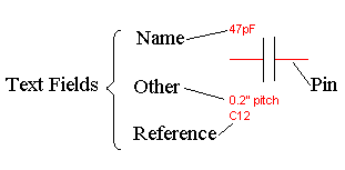
Each symbol has at least two text attributes associated with it. You can move its text fields around by selecting the symbol for editing, and then clicking on the field you wish to move. The field will now move with the mouse.
The Name attribute
This is the name or type of the component that the symbol represents. If the component has a value then insert the value here. For example, if it were a resistor then the name might be 330R or 4k7. If the symbol represents a phono connector then the name might be Phono.
This is an identifier that is unique to the whole design, typical values might be R1 or Q3 etc. There may be many resistors each with a Name field of 330R, however, each resistor must have a unique Reference. There should only be one symbol with reference R1 in a design.
This field can normally be left as it is, you can use the Special tools to set the references automatically. Either use the reference painter to “paint” each reference or use the add symbol references automatically.
This is the attribute is used for PCB netlist export. The PCB layout program will use this attribute to determine which pad layout to use. There is no fixed naming convention for this attribute and it is entirely dependent on the footprint libraries supplied with your PCB layout program.
Not all symbols have the package attribute by default. You must add it if you wish to export to a PCB program. To add it, simply click on the “Add” button, and then rename the new attribute to Package.
You may add additional attributes to a symbol from the symbol's tool dialogue. There is no real limit to the number of attributes you add. You may use these references for almost any purpose, for example you may wish to add PCB layout instructions here.
All of the the symbols in the supplied libraries have an “other” attribute already defined for you. However, you can add more if you wish. Either add them by default by editing the symbol in the library or add them individually to each symbol at placement time.
Placing Wires
 Wires
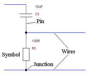
are used for connecting components of your design.
For wiring to work properly you must make sure you are using the wiring tool. This is the BLUE line in the drawing toolbar. Don't use the polygon/polyline tool – it functions very differently.
Drawing wires is now simpler than ever in TinyCAD. Select the wire tool from the drawing toolbar. Move to the where you wish to start the wire from. You may either drag out the wire to the destination or you can click once and move the mouse to the second point and click again.
When you get to the destination of the wire a red circle will indicate that the wire has snapped to the symbol or wire.
If you can't get to the destination with just two wires, then click with the mouse to place a wire corner. You may then continue until the you have placed all of the wires you need.
To cancel placing a wire right click or select another tool in the toolbars.
Automatic Junction placement
Junctions are placed automatically for you, so normally you don't need to use the junction tool.
Where two wires cross they are not considered joined unless a junction is used at the crossing point. Junctions are also required when a pin is connected to the middle of a wire.
If you wish to place junctions manually, then switch automatic junction placement off, in the Options->Settings dialogue, and then the junction tool will be available to you.
Whilst automatic junction placement is on, you cannot select junctions.