
Select an editable patch. > Modify panel > Expand the editable patch in the stack display. > Vertex sub-object level
Select an editable patch. > Modify panel > Selection rollout > Vertex button
Select an editable patch. > Right-click the patch > Tools 1 (upper-left) quadrant of the quad menu > Sub-objects > Vertex
While at the Editable Patch (Vertex) level, you can select single and multiple vertices and move them using standard methods. You can also move and rotate vector handles, thus affecting the shapes of any patches connected to the vertex.
Procedures
To transform either vertices or vectors:
At Patch (Vertex) level, with Selection rollout > Filter group > Vertices turned on, select vertices in the patch object you want to transform.
Vertices and their vectors both appear.
Turn off one of the filters, leaving the other on, and choose a transform.
A transform cursor appears when you move onto a vertex or vector in the selection set. You can toggle between filters to alternatively transform either component.
To switch vertex types:
Right-click a patch vertex.
Choose from commands on the quad menu. The Tools 1 (upper-left) quadrant includes two options specific to patch vertices:
Coplanar: If you set a patch control point's property to be coplanar, it's like locking the handle of the outgoing vector for that point. Moving a handle attached to a coplanar vertex causes the opposite vectors to adjust their positions to maintain a coplanar surface. This option is the default and gives smooth transitions between patches.
Corner: If you set a patch control point's property to be corner, it unlocks the handle of the outgoing vector, so you can create a discontinuous break in the patch surface.
To switch vertex types from Coplanar to Corner, do one of the following:
Hold down SHIFT as you move a handle of a Coplanar vertex.
This switches the vertex type to Corner.
If Lock Handles is turned off (the default), SHIFT-Move "breaks" the handle, allowing it to move independently.
If Lock Handles is turned on, the handles remain locked in their coplanar relationship. However, the vertex is still switched to Corner, and turning off Lock Handles lets you move the handles separately.
Right-click the vertex, and choose Corner from the quad menu.
To delete a vertex:
At Patch (Vertex) level, select a vertex.
Click Delete.
The vertex and all patches sharing this control point are deleted.
Deleting vertices
To weld vertices:
At Patch (Vertex) level, select two valid vertices on different patches.
Set Weld Threshold to a value at least equal to the distance between the selected vertices.
Click Weld.
The two vertices move together and join.
Welding vertices
To transform interior vertices:
Using program defaults, you can select only vertices and vectors on the outer edge or boundary of a patch. This default is known as Auto Interior.
In some cases, you might want to move the interior vertices. For example, you might want to tweak a patch's curvature without having to subdivide the patch. At Patch level, you can change the default on a patch-by-patch basis by right-clicking a patch and choosing Manual Interior from the shortcut menu. This lets you select and transform individual interior vertices. These vertices appear as yellow squares in the viewports.
Warning: If you return a patch to the default, changes due to Manual Interior are lost.
Note: Certain objects, such as the TeapotTeapot, are automatically set to Manual Interior when converted to patch objects. In such cases, you can see all interior vertices when you go to the Vertex sub-object level.
Interface
Selection rollout
For information on these settings, see Editable Patch.
Soft Selection rollout
See Soft Selection Rollout for information on the Soft Selection rollout settings.
Geometry rollout

When Edit Patch is the active modifier and the Vertex sub-object level is active, the Geometry rollout on the Modify panel has the options listed below.
Subdivision group
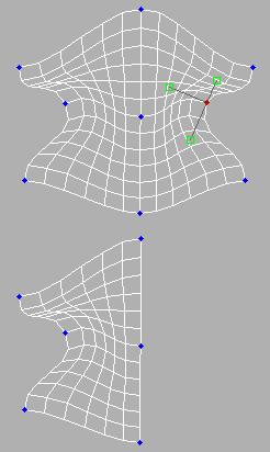
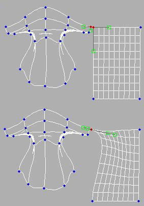
Bind: Lets you create a seamless, gapless connection between two patch edges that have unequal numbers of vertices. The two patches must belong to the same object, and the vertex need not be selected first. Click Bind, then drag a line from an edge-based vertex (not a corner vertex) to the edge you want to bind it to. The cursor turns into a white cross when over a legal edge.
Binding patch edges
To exit Bind mode, click the Bind button again, or right-click in the active viewport.
Tip: When connecting two patches edge-to-edge, first line up as many pairs of vertices as possible, and use Weld to connect them. Then use Bind to connect the remaining vertices. Bound vertices cannot be manipulated directly, although their handles can.
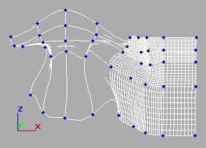
Note: Bind is useful for connecting patch objects with different patch resolutions, such as a head and a neck, without the need to create additional patches in the lower-resolution object.
Unbind: Disconnects a vertex connected to a patch with Bind. Select the vertex, and then click Unbind.
Topology group
Create: Creates freestanding vertices.
Attach: Attaches an object to the currently selected patch object. Click the object you want to attach to the currently selected patch object.
For further details, see Attach.
Reorient: When on, reorients the attached patch so that each patch's creation local coordinate system is aligned with the creation local coordinate system of the selected patch.
Delete: Removes vertices from the framework. Use this option with caution. Deleting a single vertex also deletes any patches that share this control point. For example, if you delete the single vertex at the top of a spherical patch object, the top four patches are also deleted, leaving a hemisphere.
Break: Breaks a vertex into multiple vertices. Use this if you need to split open an edge to add another patch or for general modeling operations. Select a vertex and then click Break. After the break select the individual vertices and move them to separate the edges.
Hide: Hides selected vertices and the attached patches.
Unhide All: Restores any hidden sub-objects to visibility.
Weld group
Selected: Welds selected vertices that fall within the tolerance specified in the Weld Threshold spinner (to the right of the Weld button). Select the vertices you want to weld between two different patches, set the spinner to a sufficient distance, and click Weld.
Target: Turn on and drag from one vertex to another to weld the vertices together. The dragged vertex fuses to the target vertex.
The pixels spinner to the right of the Target button sets the maximum distance in screen pixels between the mouse cursor and the target vertex.
Surface group
View Steps: Controls the grid resolution of the patch model surface as depicted in the viewports.
Show Interior Edges: Enables the display of the patch object's interior edges in wireframe views. When off, only the object's outline is visible. Turn on to simplify the display for faster feedback.
Surface Properties rollout

Edit Vertex Colors group
Use these controls to assign the color, illumination color (shading), and alpha (transparency) values of selected vertices.
Color: Click on the color swatch to change the color of selected vertices.
Illumination: Click on the color swatch to change the illumination color of selected vertices. This lets you change the color of shadows without changing the vertex colors.
Alpha: Lets you assign an alpha (transparency) value to selected vertices.
The spinner value is a percentage; zero is completely transparent and 100 is completely opaque.
Select Vertex By group
Color and Illumination radio buttons: These buttons determine whether to select vertices by vertex color values or vertex illumination values.
Color Swatch: Displays the Color Selector, where you can specify a color to match.
Select: Depending on which radio button is selected, selects all vertices whose vertex color or illumination values either match the color swatch, or are within the range specified by the RGB spinners.
Range: Specifies a range for the color match. All three RGB values in the vertex color or illumination must either match the color specified by the Color swatch in Select By Vertex Color, or be within plus or minus the values in the Range spinners. Default=10.