
Select an editable patch. > Modify panel > Expand the editable patch in the stack display. > Element sub-object level
Select an editable patch. > Modify panel > Selection rollout > Element button
Select an editable patch. > Right-click the patch > Tools 1 (upper-left) quadrant of the quad menu > Sub-objects > Element
Use the Element sub-object level when you want to select and work on all contiguous faces in an element. The Element sub-object level is essential when you are SHIFT-cloning and SHIFT-extruding patches, because doing so creates separate elements. For example, if you select a patch, hold down the SHIFT key, and move the patch to a new location, a new element is created separate from the original. This also applies to extrusion. If you hold the SHIFT key down while you extrude, a new element is created.
Note: In some cases, you might find that moving a patch element causes parts of it to move by differing amounts. This typically occurs because the object is set to Manual Interior. It happens, for instance, when you convert a sphere primitive to an editable patch object. To remedy this, select the element, and then right-click it to display the quad menu, and in the Tools1 quadrant, choose Auto Interior.
Interface
Selection rollout
See Editable Patch for information on the Selection rollout settings.
Soft Selection rollout
See Soft Selection Rollout for information on the Soft Selection rollout settings.
Geometry rollout

Subdivision group
Subdivide: Subdivides selected elements. Select one or more elements, and then click Subdivide.
Propagate: When on, extends the subdivision to neighboring patches. Propagating the subdivisions along all contiguous patches prevents patch cracks where you have attached patches together.
Topology group
Create: Creates a three or four-sided patch on existing geometry or in free space. First turn on Create and then click on geometry or free space in the viewports to create a quad or a tri patch.
The cursor changes to a white cross hair when over an existing patch vertex. Select an existing vertex by clicking it. Click in free space to create a new vertex at that location; this vertex is included in the sequence of vertices for the new patch.
To create a Tri Patch: Click three times in free space or on existing vertices. Right-click, or left-click on one of the vertices in the current sequence to complete the creation of a Tri Patch.
To create a Quad Patch: Click four times in free space or on existing vertices. The Quad Patch will be automatically created after the fourth click.
No operation will take place if you right-click or select a vertex in the current sequence when only one or two vertices are in the sequence.
Detach: Lets you select one or more elements within the current object and then detach them (or copy them) to form a separate patch object.
Reorient: When on, the detached patch element copies the position and orientation of the source object's creation Local coordinate system. The new detached object is moved and rotated so that its Local coordinate system is positioned and aligned with the origin of the current active grid.
Copy: When on, the detached patch elements are copied to a new patch object, leaving the originals intact.
Attach: Lets you attach an object to the currently selected patch object. Click the object you want to attach to the currently selected patch object.
For further details, see Attach.
Reorient: When on, reorients the attached element so that each patch's creation local coordinate system is aligned with the creation local coordinate system of the selected patch.
Delete: Deletes the selected element.
Hide: Hides selected elements.
Unhide All: Restores any hidden sub-objects to visibility.
Extrude & Bevel group
These controls let you extrude and bevel all patches in an element or elements. Extruding patches moves them along a normal and creates new patches that form the sides of the extrusion, connecting the selection to the object. Beveling adds a second step that lets you scale the extruded patches. You can extrude and bevel patches by dragging or by direct entry. You can also hold down the SHIFT key during extrusion, which creates a separate element.
Note: Sides created by beveling or extrusion are assigned to smoothing group 1.
Extrude: Click this button, and then drag any element to extrude it interactively. Hold down the SHIFT key during this operation to create a new element.
When the mouse cursor is over a selected element, it changes to an Extrude cursor.
Bevel: Click this button, and then drag any element to extrude it interactively, then click and release the mouse button, and drag again to bevel the extrusion. Hold down the SHIFT key during this operation to create a new element.
When the mouse cursor is over a selected element, it changes to a Bevel cursor.
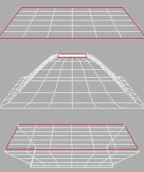
Original patch (top) and inward and outward extrusions
Note: In some cases, particularly with closed objects (objects with no holes or open edges), the second bevel step might not produce visible results.
Extrusion: This spinner lets you extrude selected elements outward or inward, depending on whether the value is positive or negative.
Outlining: This spinner lets you scale selected elements bigger or smaller, depending on whether the value is positive or negative. It is normally used after an extrusion for beveling the extruded patches.
Normal: If Normal is set to Local (the default), extrusion takes place along the individual normals of patches in selected elements. With Normal set to Group, extrusion takes place along the averaged normal of all patches in selected elements.
Bevel Smoothing: These settings let you set the shape of the intersection between the surface created by a beveling operation and the neighboring patches. The shapes are determined by the handle configurations of vertices at the intersections. Start refers to the intersection between the sides and the patches surrounding the beveled patch. Finish refers to the intersection between the sides and the beveled patch or patches. The following settings are available for each:
Smooth: Vertex handles are set so the angles between the new patches and their neighbors are relatively small.
Linear: Vertex handles are set to create linear transitions.
None: Vertex handles are not modified.
Warning: Set Bevel Smoothing before the bevel is performed; changing the setting has no effect on existing beveled patches.
Surface group
View Steps: Controls the grid resolution of the patch model surface as depicted in the viewports.
Show Interior Edges: Enables the display of the patch object's interior edges in wireframe views. When off, only the object's outline is visible. Turn on to simplify the display for faster feedback.