Select an object. > Modify panel > Modifier List > UV Coordinate Modifiers > Unwrap UVW > Edit button (on Parameters rollout)
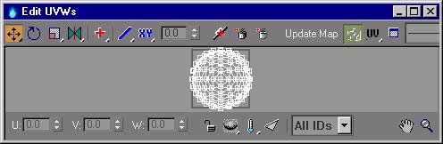
The Edit UVWs dialog is a window that displays a lattice made up of UVW faces and UVW vertices. There is a UVW face for every face in a mesh. A UVW face has three vertices. The view window displays the UVWs in the 2D-image space of the map. A black rectangle displays the boundaries of a texture map as it would appear in image space (the lower-left corner of the rectangle has the coordinates (0,0) and the upper-right has the coordinates (1,1). Within this window, you manipulate the UVW coordinates relative to the map (or mesh) by selecting the lattice vertices and moving them.
The state of the Edit UVWs dialog, including buttons and selected options, is stored and recalled the next time you open the Edit dialog.
Interface
Toolbar
Contains all the controls for manipulating the texture vertices in the view window, navigating within the window, and setting other options. Pressing the CTRL and ALT keys and applying the transform can center all texture vertex transforms. The initial click specifies the center of the transform.
 Move: Moves selected vertices. Flyout options are Move, Move Horizontal, and Move Vertical. Press SHIFT to constrain the movement to a single axis.
 Rotate: Rotates selected vertices.
 Scale: Scales selected vertices. Flyout options are Scale, Scale Horizontal, and Scale Vertical.
 Mirror: Mirrors selected vertices and flips UVs. Flyout options are Mirror Vertical, Mirror Horizontal, Flip Horizontal, and Flip Vertical.
Flip first detaches the selected vertices along their boundary edge and then applies a Mirror Horizontal or Vertical depending on the mode.
 Expand/Contract Selection: Expands or contracts vertex selection. Flyout options are Expand Selection and Contract Selection.
First select a point, and then click Contract or Expand repeatedly to expand or contract the vertex selection.
 Falloff Type: Moves, rotates, or scales non-selected vertices based on the value set in the Falloff Distance field, and the falloff type. Flyout options are Linear, Sinal, Slow Out, and Fast Out.
First enter a value in the distance field, and then click and drag a point.
 Falloff Space: Selects object or texture space for the falloff distance. XY selects object space, UV selects texture space.
Falloff Distance field: Sets falloff distance. As values increase, unselected vertex color changes gradually from the selected vertex to reflect the sphere of influence.
First, set a value that encompasses vertex to be moved or scaled, and then click and drag to move or scale vertices with a falloff effect.
 Break: Replaces a single shared vertex with two vertices. If two faces share a vertex, Break creates two vertices.
 Target Weld: Welds selected vertices to a single target vertex.
Turn on Target Weld, select vertices, and then drag the selected vertices to the target vertex.
 Weld Selected: Welds selected vertices to a single vertex based on the Weld Threshold. To set a weld threshold, click UVW Options on the Edit UVW toolbar, and change the Weld Threshold value.
Update Map: Updates the map in the view window to match the current version. For speed, the map is cached and instanced from the original, it is not automatically updated if it changes. (For example, an animated map can slow the system down when you move from frame to frame.)
 Show Map: Toggles the display of the map in the view window.
 UV/VW/UW: As a default, the UV portion of the UVW coordinates is displayed in the view window. However, you can switch the display to edit the UWs or the VWs.
 Unwrap Options: Click to display the Unwrap Options dialog.
Pick Texture: Contains all the maps of the material assigned to the object. The names of the maps, assigned in the material editor, are displayed in the list. The Pick Texture option in the list allows you to add and display textures that are not in the object's material. A total of 10 maps can be stored in the list; additional maps scroll off the bottom of the list.
Select a map you want to use in the view window. For example, select a bump or texture map as a reference to move UVW vertices.
Lower Toolbar
U, V, and W: Use the keyboard or use the spinners to enter UVW vertex coordinates.
 Lock Selection: Locks vertex selection. You can move selected vertices without touching them.
 Hide/Unhide: Hides or unhides selected vertices in the view window. The flyout options are Hide and Unhide.
 Freeze/UnFreeze: Freezes selected vertices or unfreezes all vertices. Frozen vertices cannot be selected or moved.
 Filter Selected Faces: Displays UVW vertices of the object's selected faces, and hides the rest.
All ID's (drop-down): Filters the objects material IDs. Displays texture faces that match the ID drop-down.
 Pan: Click Pan, and then click+drag to pan the window.
 Zoom: Click Zoom, and then click+drag to zoom the window.
 Zoom Region: Click Zoom Region, and then region-select part of the window to zoom in.
 Zoom Extents: Zoom extents all UVW vertices or only selected UVW vertices. The flyout options are Zoom Extents and Zoom Extents Selected.
![]() Pixel Snap: Snaps to the nearest pixel when you have a bitmap in the background. Combine this with Mid Pixel snap option in Unwrap Options to snap to the center rather than the pixelÆs edge.
Pixel Snap: Snaps to the nearest pixel when you have a bitmap in the background. Combine this with Mid Pixel snap option in Unwrap Options to snap to the center rather than the pixelÆs edge.
Edit UVW Window
The Edit UVW window allows you to edit UVW vertices to adjust the map on a model. One texture map may have the side, top, and front views of a car. By first planar mapping the top, side, and front faces of the model in Sub-Object Selected Face, you can adjust the UVW vertices for each selection, to line up the texture map to the car.
To edit the UVW vertices, first choose a transform tool, and then click and drag in the window to transform the selected vertices.
Right-click menu: Right-click in the window to display the right-click menu. All the transform tools are available on the right-click menu.